Final Project: Overview and Documentation
Demo Video:
Motivation
The motivation for my final project came from a YouTube video by Liam Thompson, linked here. In the video, he builds an elevator for his cat, Frodo, who was 19 years old at the time and had difficulty getting around the house. At the time of writing this, Frodo has unfortunately passed away. After hearing the news, I realized that I had grown attached to Frodo- a cat across the world that I had never even seen in-person- but his passing mid-way through the semester was a major motivator for me to take on the project in earnest. Apart from older animals, there are also pets with disabilities. And some breeds, in particular the dachshund and the chihuahua, have body morphologies that are not suited for climbing the stairs. Additionally, puppies and kittens may have difficulty due to their size and unsteadiness on their paws. I also wanted to take on the engineering challenge of trying to make the elevator adjustable both in terms of length and angle relative to the ground.
Project Documentation: Fabrication
Planning the build was arguably the hardest part of the process. I invested a lot of time into thinking about potential solutions to the issues of length and angle correction of the carriage. For example, what would be the best (feasible) way to make the frame itself extendable? Since extending the frame also means adjusting the length of the timing belt, how could I do that most effectively? And if the length of the elevator frame can vary, how could I program the stepper motor to stop at the top and bottom of the stairs given that counting steps was not an option? How could I adjust the carriage so that it was parallel to the ground regardless of the angle of the elevator?
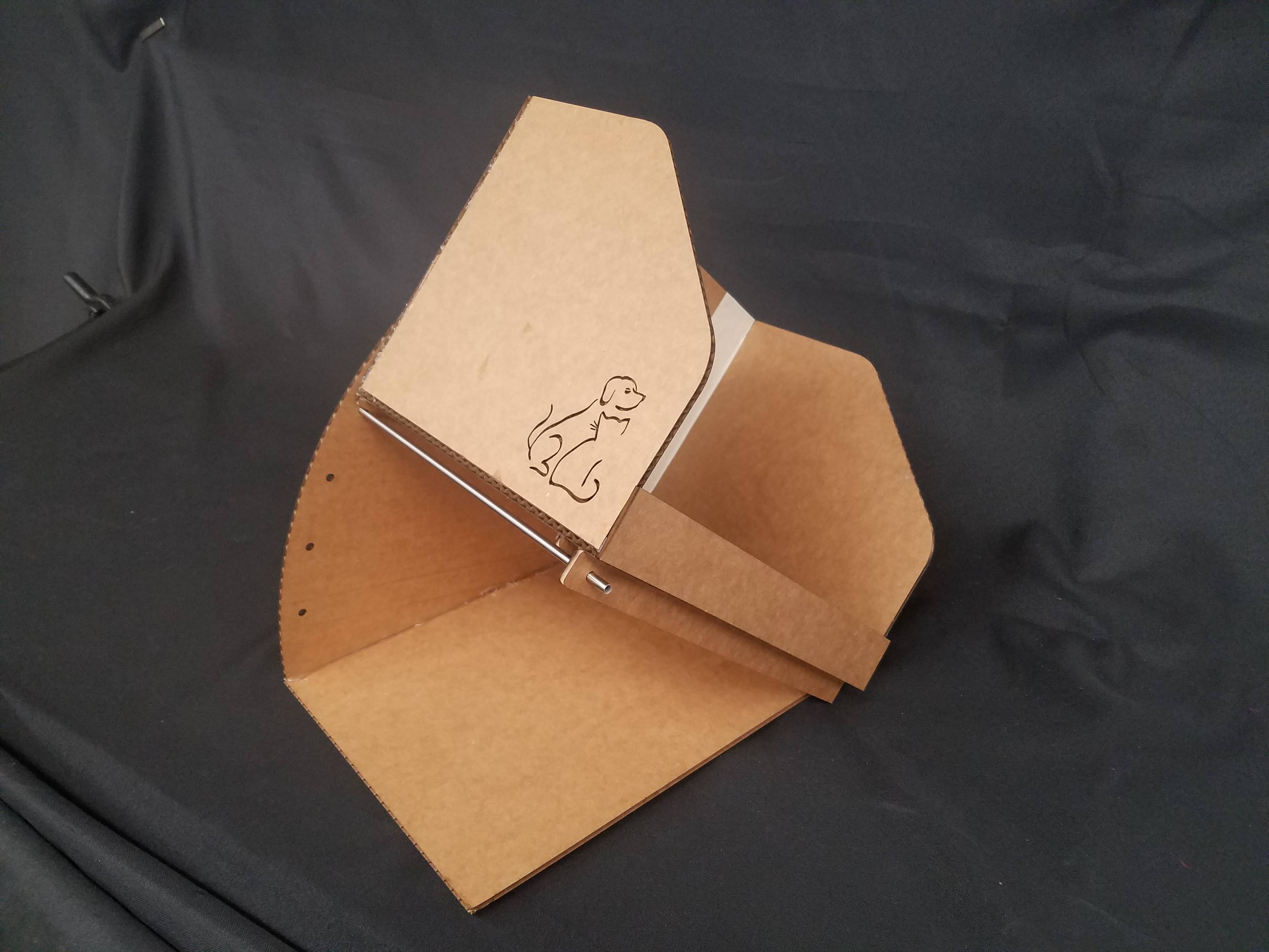
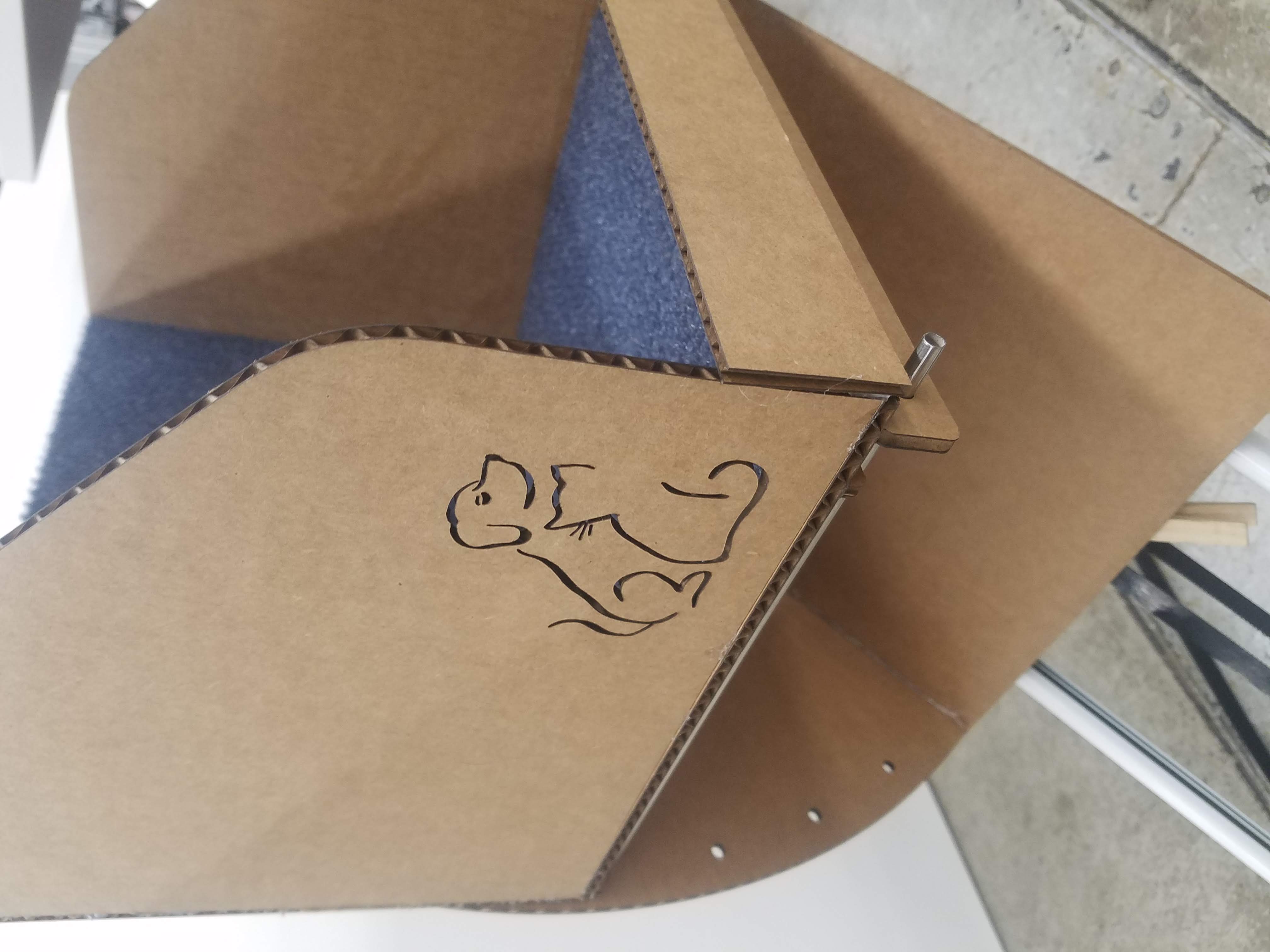
I first started with something fairly straightforward. That is, the carriage itself. I knew the way I wanted it to look, and it was not difficult to sketch in Fusion 360. I also converted a .png file I found online into a .svg file and imported it into the sketch- this became the dog and cat on the side of the carriage. I laser cut these parts from cardboard and used hot glue and tape to assemble them.
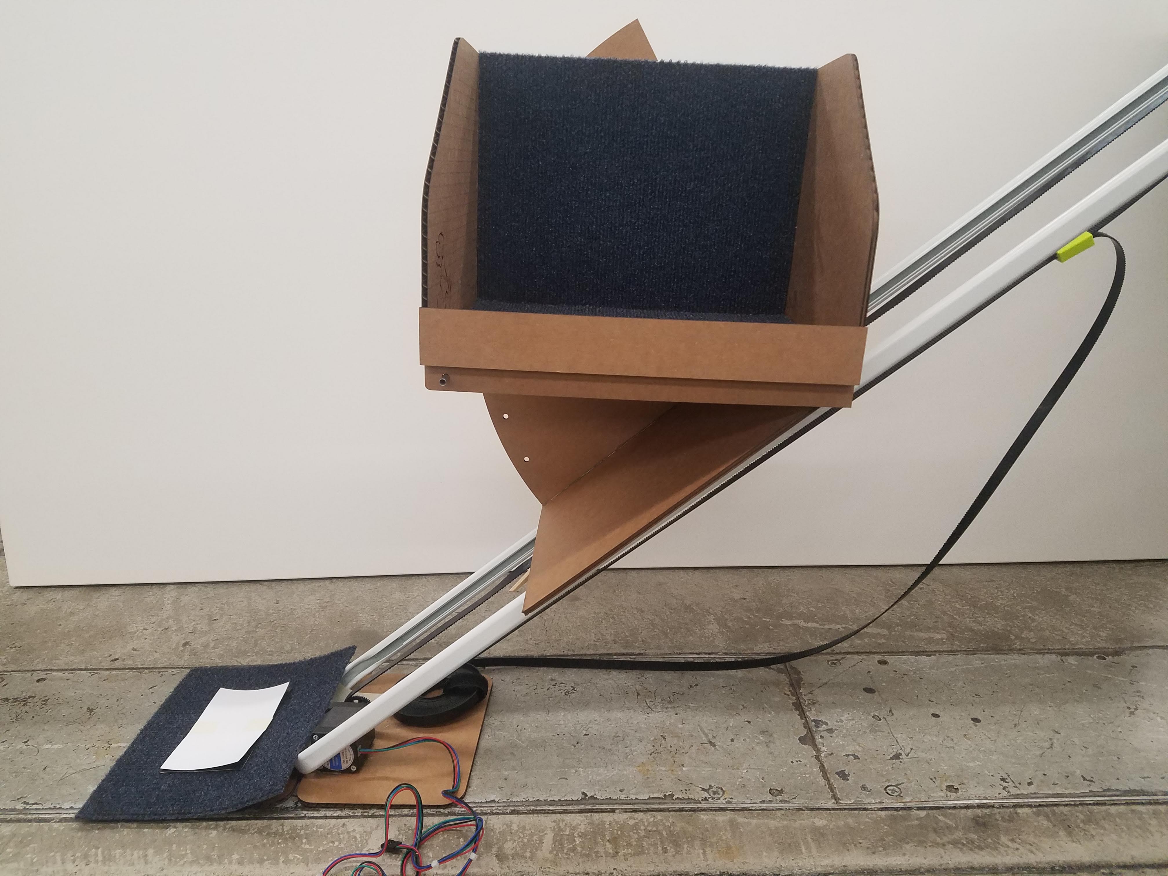
Then, I diverted my attention to the problem of adjusting the angle of the carriage. In hindsight, there were several potential candidate mechanisms, but I am happy with the one I thought of and successfully implemented. The mechanism I arrived at was fairly simple- 5 pieces of cardboard (including the two small nubs attached directly underneath the carriage). The main piece was made by sketching a circle in Fusion 360 and leaving only a 100° slice of the pie. In this piece, I added small holes at 10° increments, such that the carriage can (theoretically) still be angled parallel to the ground when the elevator is perpendicular to it. This piece was connected to a "baseplate" of sorts using hot glue. The baseplate, in turn, was connected at the back to one side of the carriage using masking tape to form a makeshift hinge. A rod goes through the piece with a hole in it attached to the bottom of the carriage and the hole in the 100° piece to hold the carriage parallel to the ground. Here is video footage and a picture of the carriage and angle adjustment mechanism.
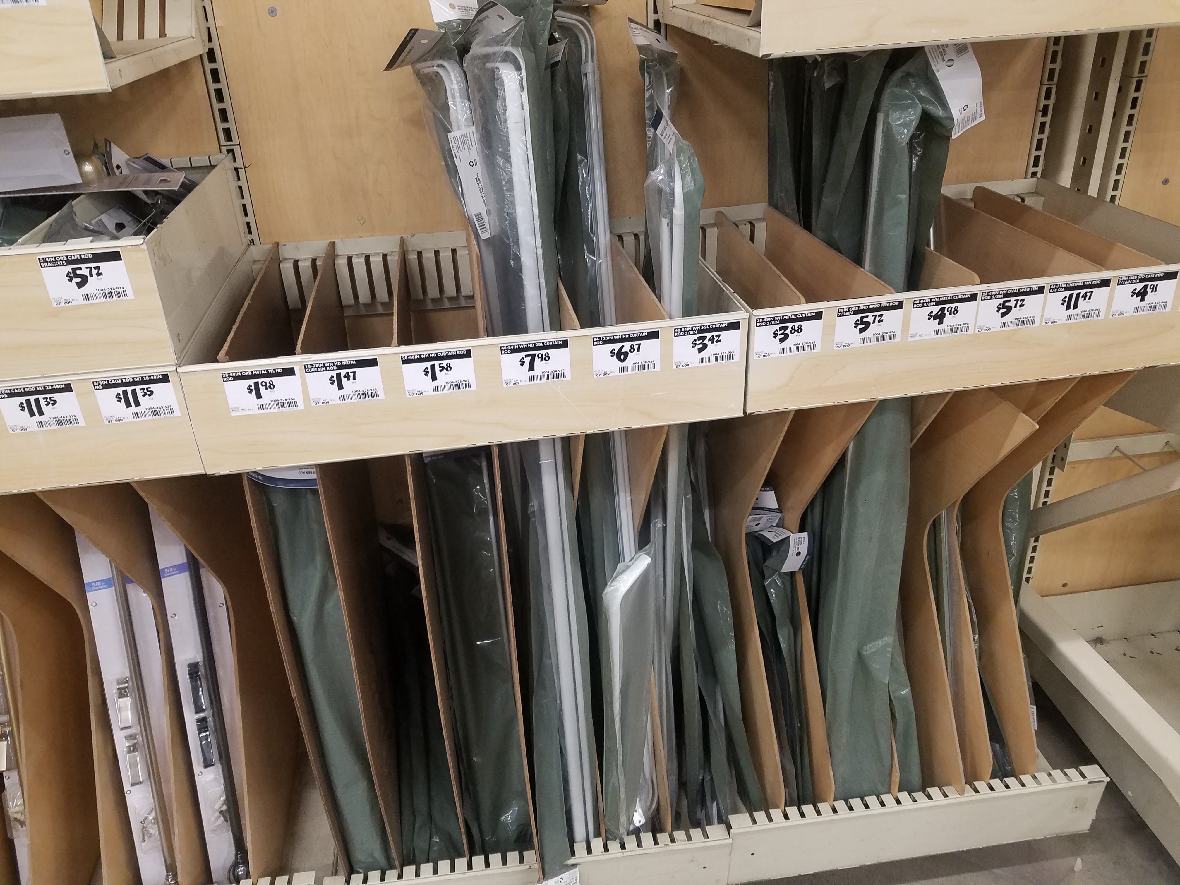
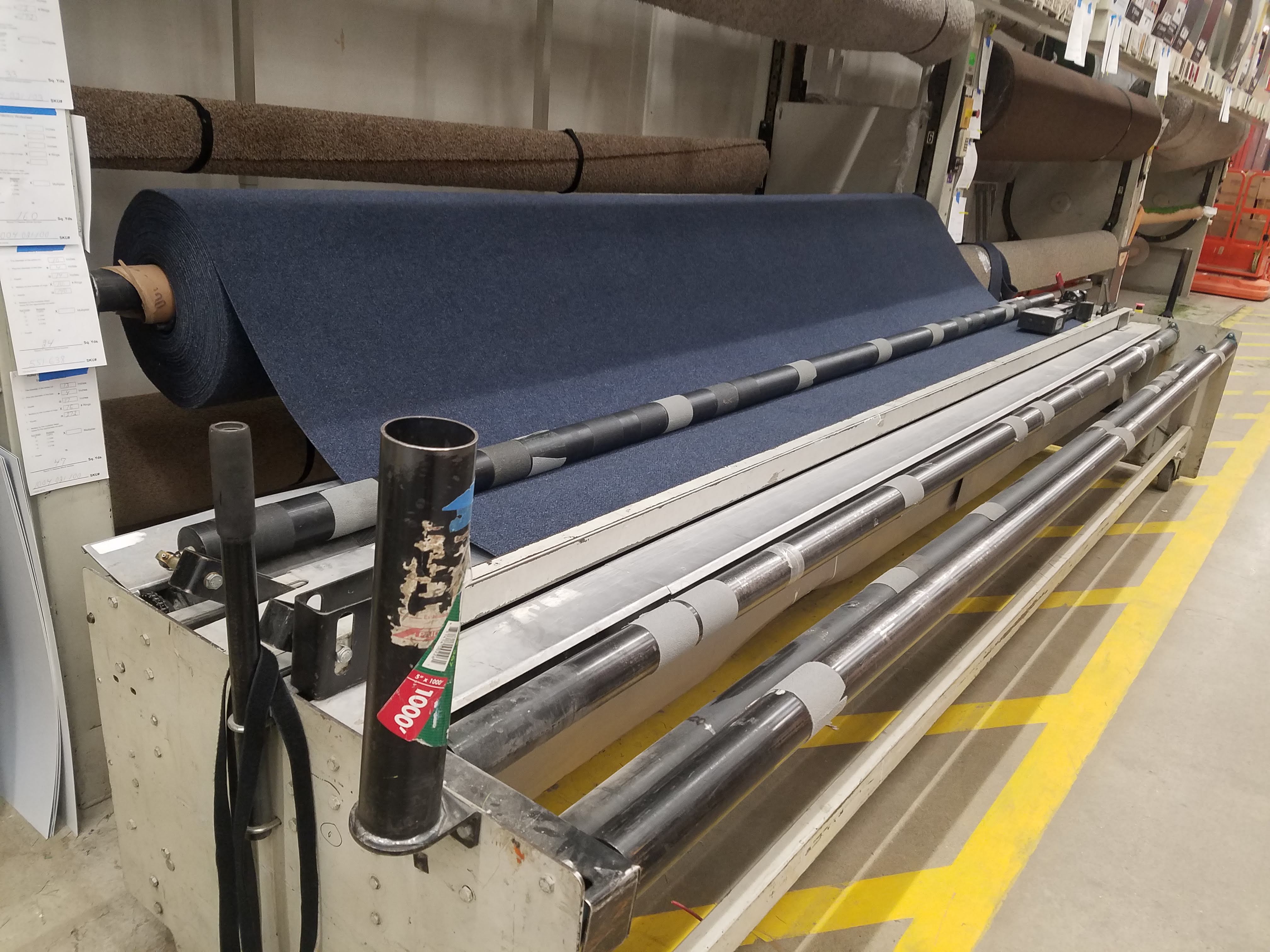
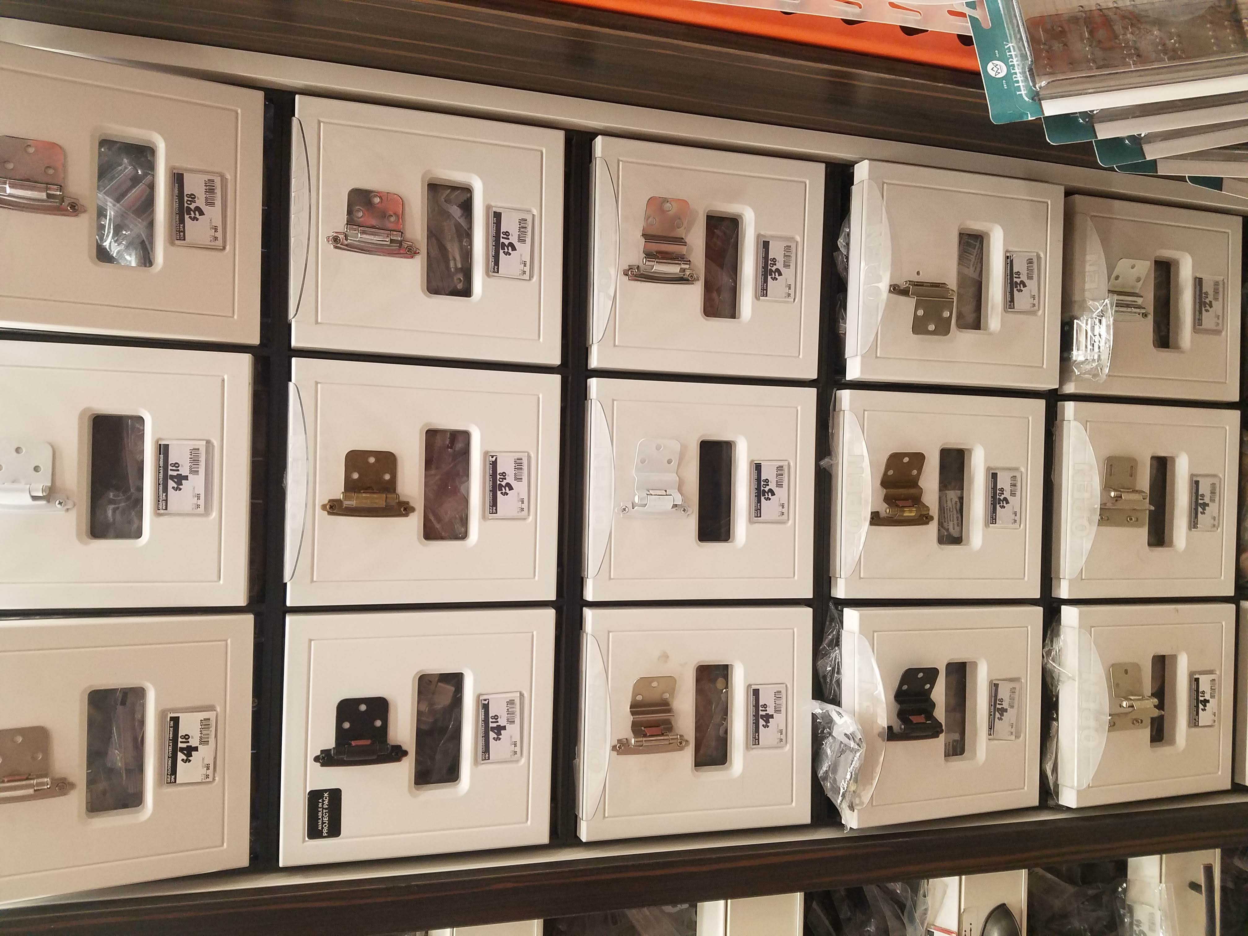
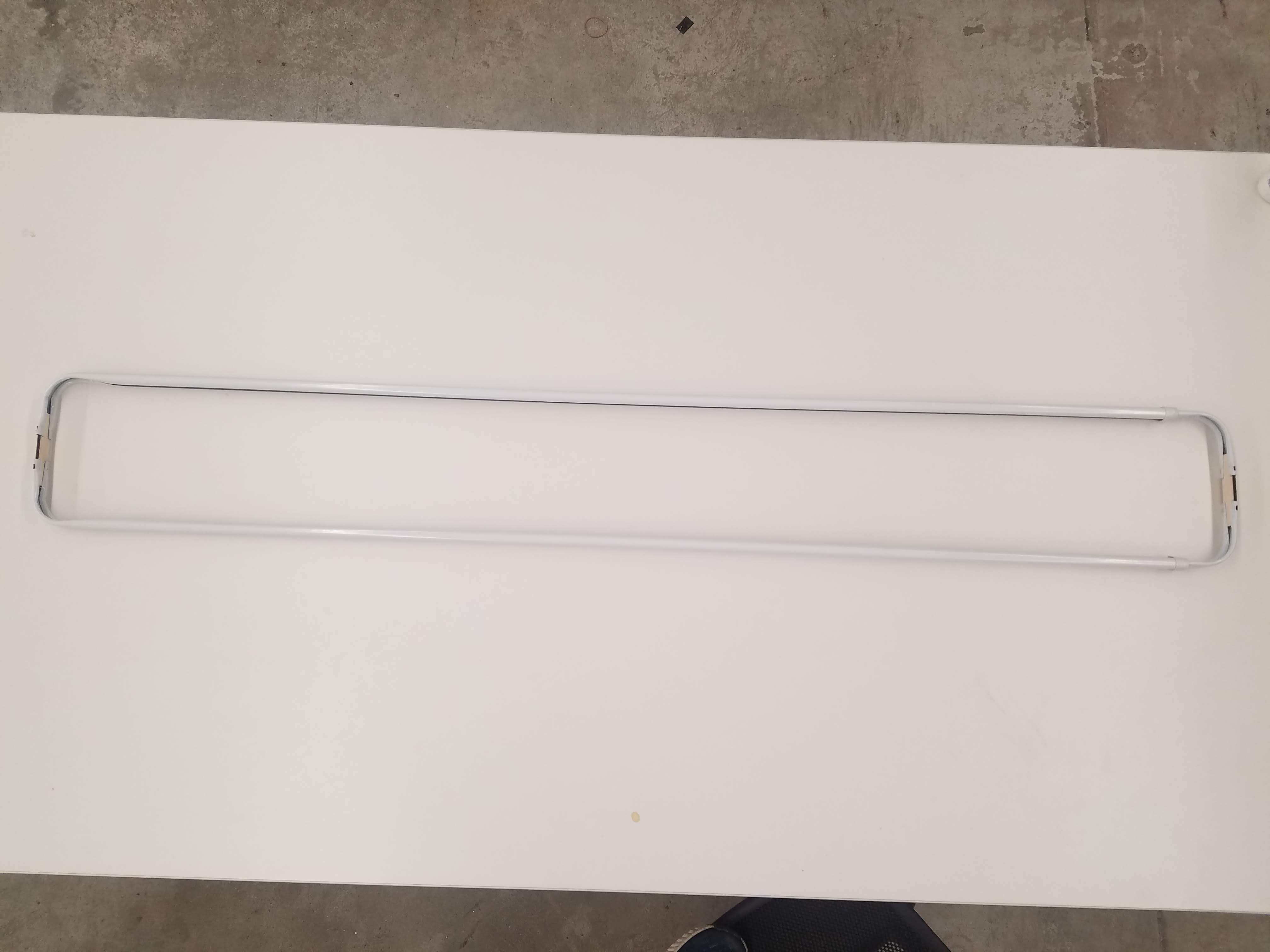
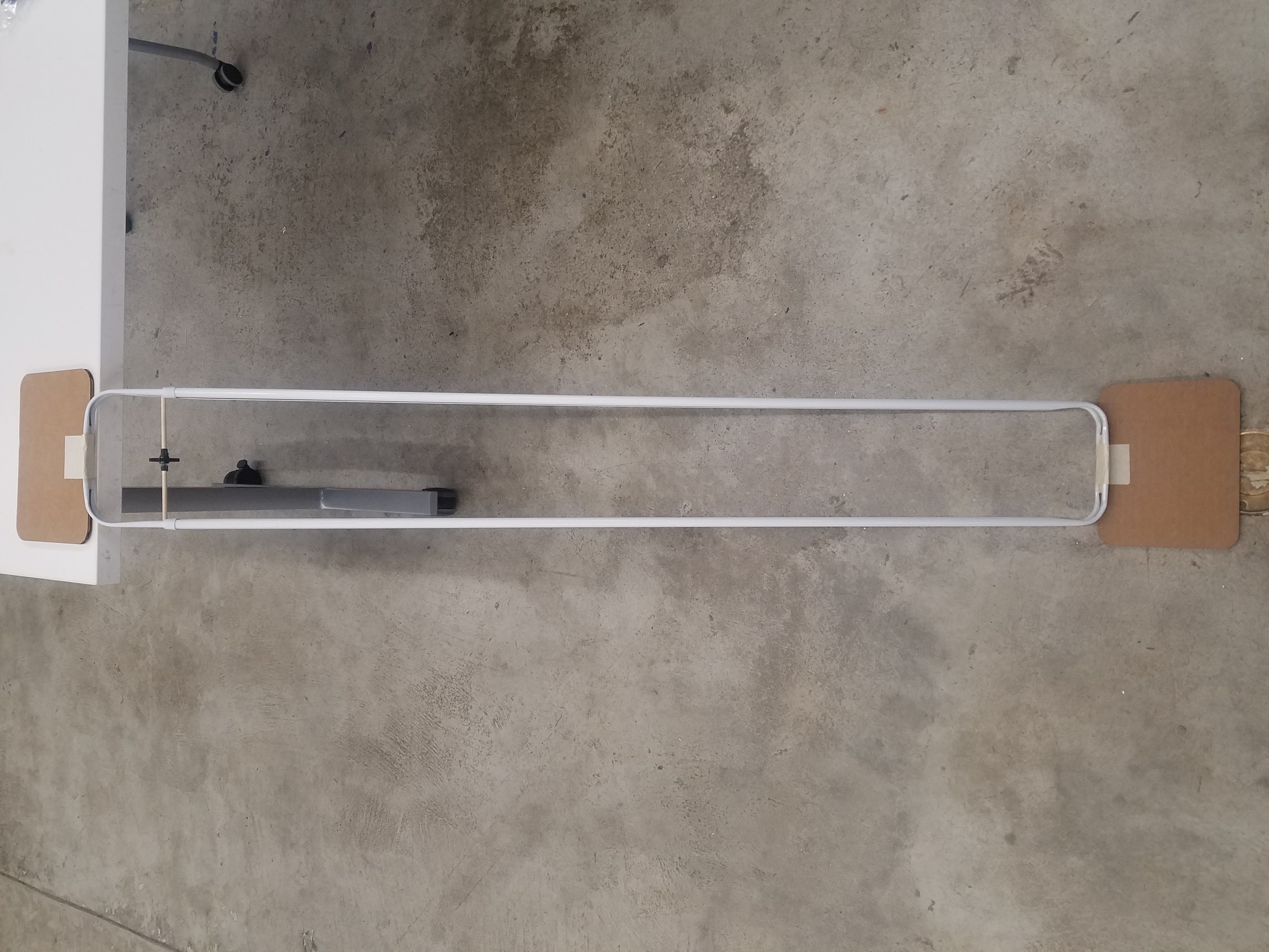
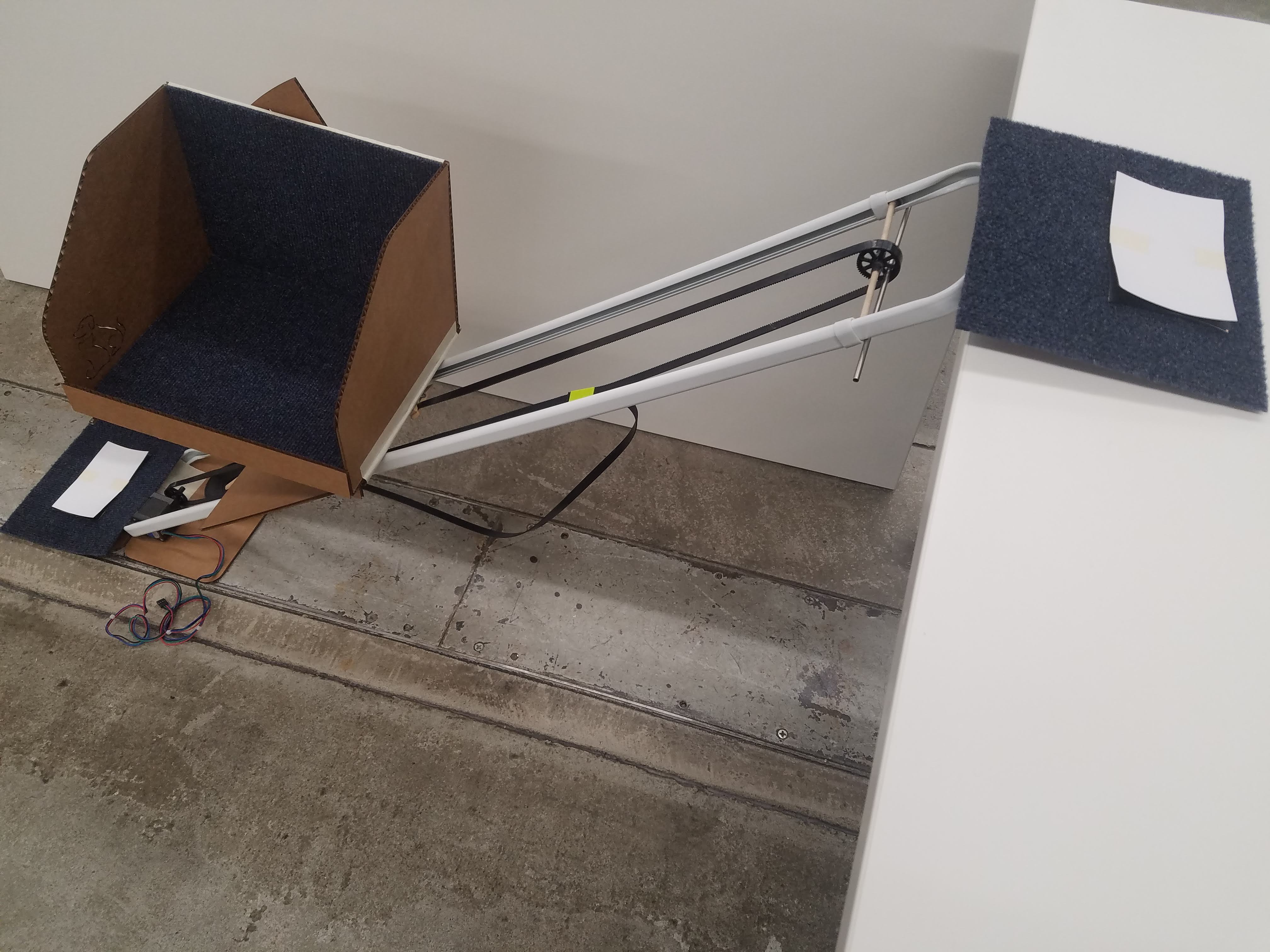
The next issue that I addressed was how to make the frame of the elevator extendable. This was actually surprisingly straightforward. I realized that two adjustable curtain rods joined together could serve as an extendable frame and headed off to Home Depot to purchase two 48" to 84" adjustable curtain rods. I also bought one square yard of carpet which I later used to decorate the inside of the carriage and the carboard supports (more on those later) as well as two metal hinges for the supports (which I ended up not using).
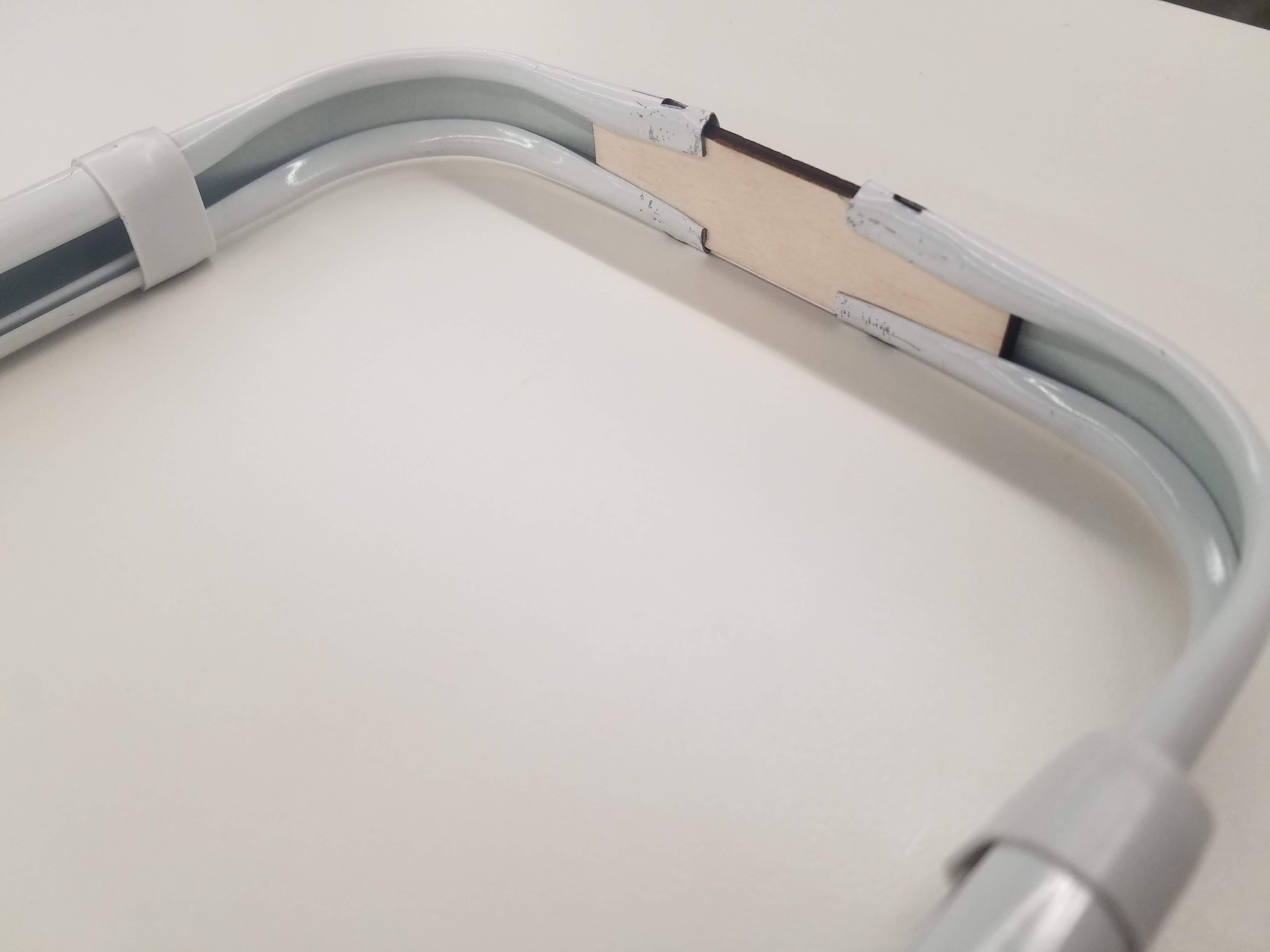
I laser cut two small, rectangular pieces of wood and used these to connect the curtain rods at either end. To make sure the frame would not come apart at these two junctions, I used pliers to pinch/crimp the metal curtain rods around the wood pieces. I also added a dollop of hot glue just to be on the safe side.
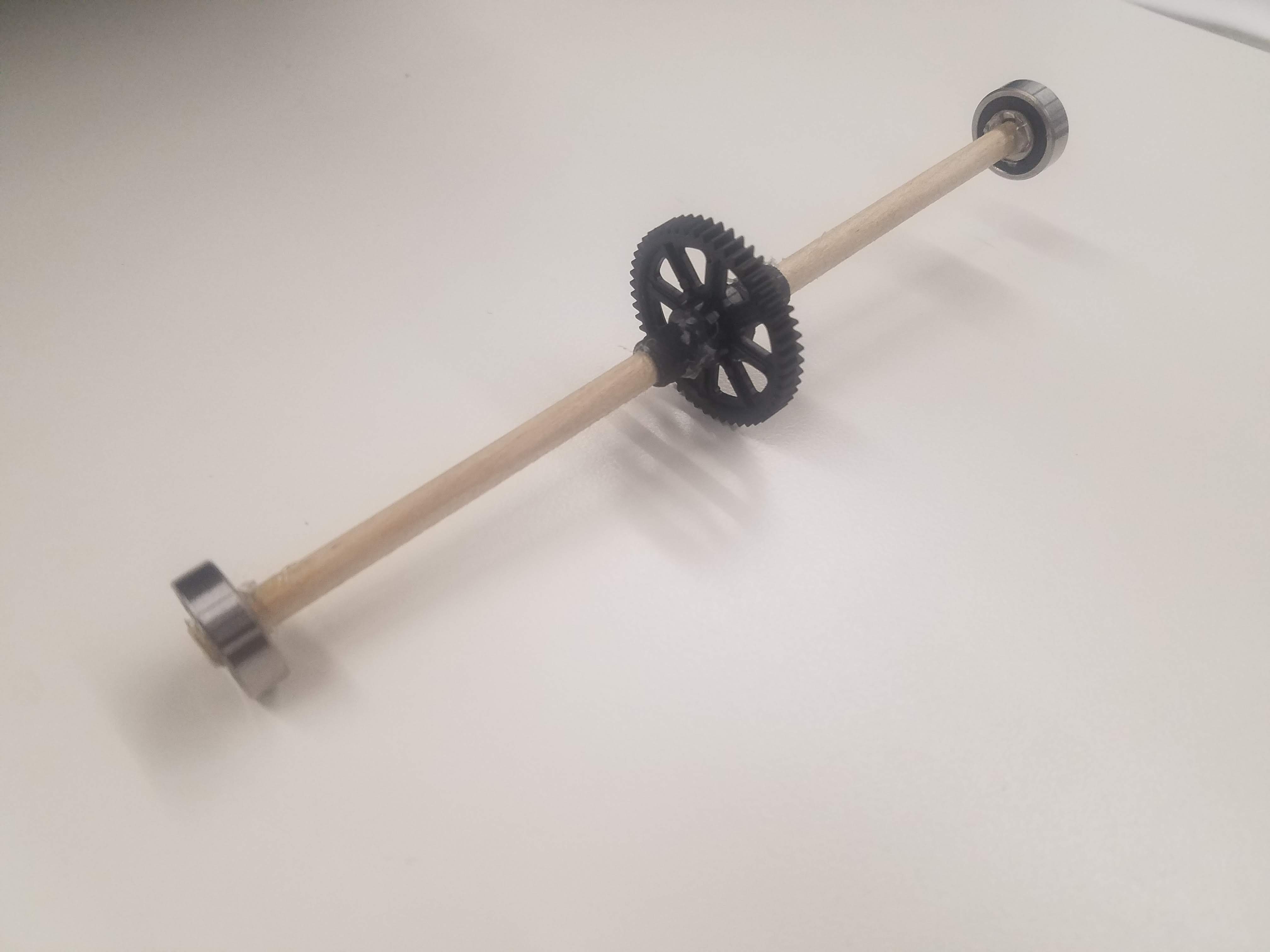
I knew that the NEMA-17 stepper motor I was going to use to drive the timing belt would be placed on the ground, and that I would need a free-spinning pulley at the opposite end to create a loop for the timing belt. However, I found that the 10mm wide timing belt I had with me did not fit into the 6mm-wide pulleys in the lab. I looked around and miraculously found two plastic gears that fit the ridges in the GT2 timing belt perfectly. These, of course, were thin gears without supports like the pulley to keep the timing belt on, and I later hot glued scrap pieces from the project just to try and keep the belt from slipping off.
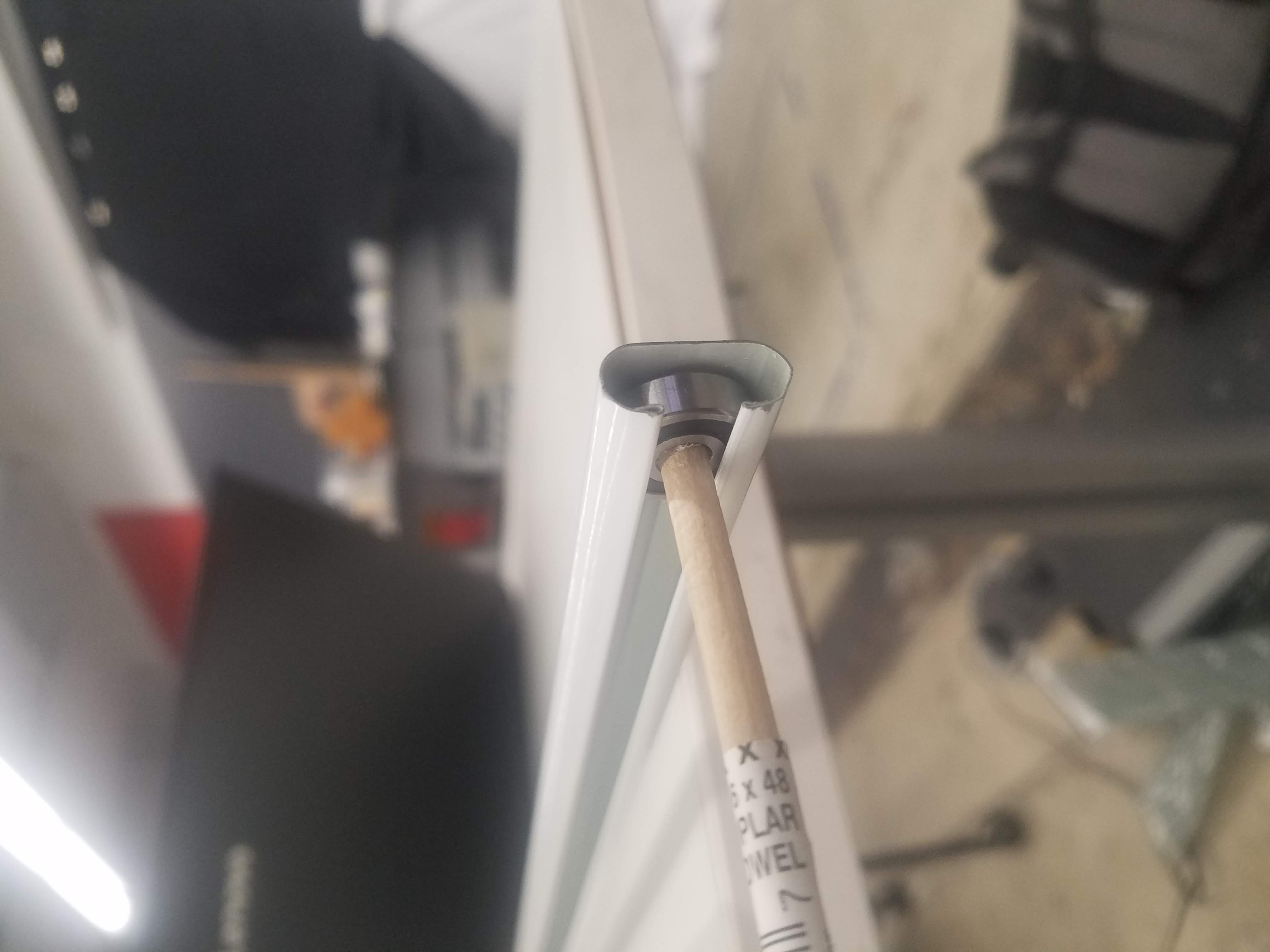
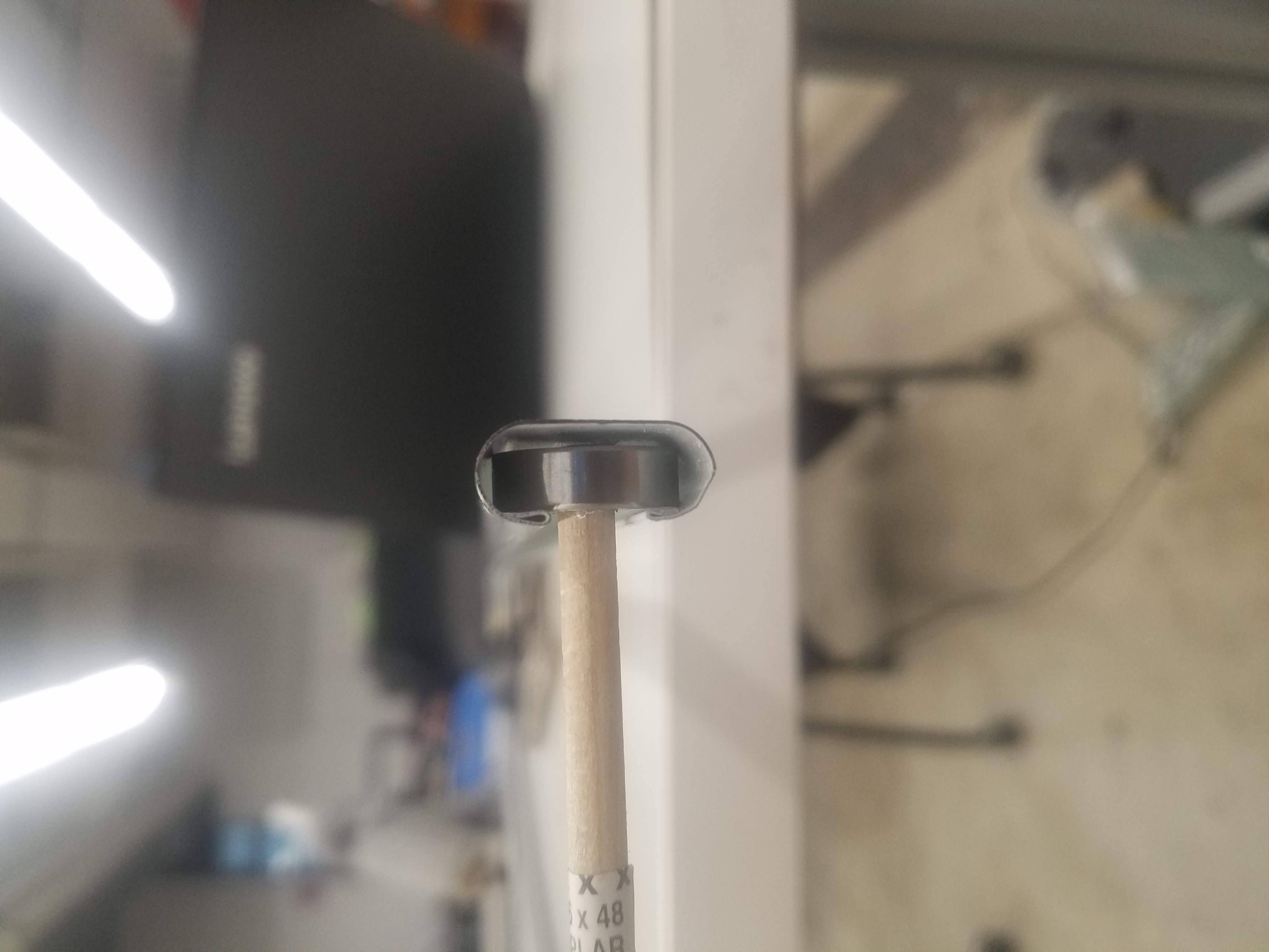
I found bearings in the lab that fit perfectly inside the curtain rods as pictured below and a wooden dowel that was the exact right fit for the inside of the bearing. I also tried metal rods, but none of them fit unfortunately. I hot glued a bearing onto one end of the dowel and then placed the gear. Since the center hole of the gears were slightly larger than both the dowel and shaft of the stepper motor, I had to wrap tape around both until I got a snug fit. After hot gluing the gears onto the dowel and the shaft of the stepper motor for good measure, I hot glued the last bearing onto the end of the wooden dowel (which I had pre-cut to fit snugly between the curtain rods). It was a really tight fit and I had to spend a considerable amount of time trying to shimmy the bearing-gear-bearing-dowel up to one of the frames. I eventually succeeded in doing so.
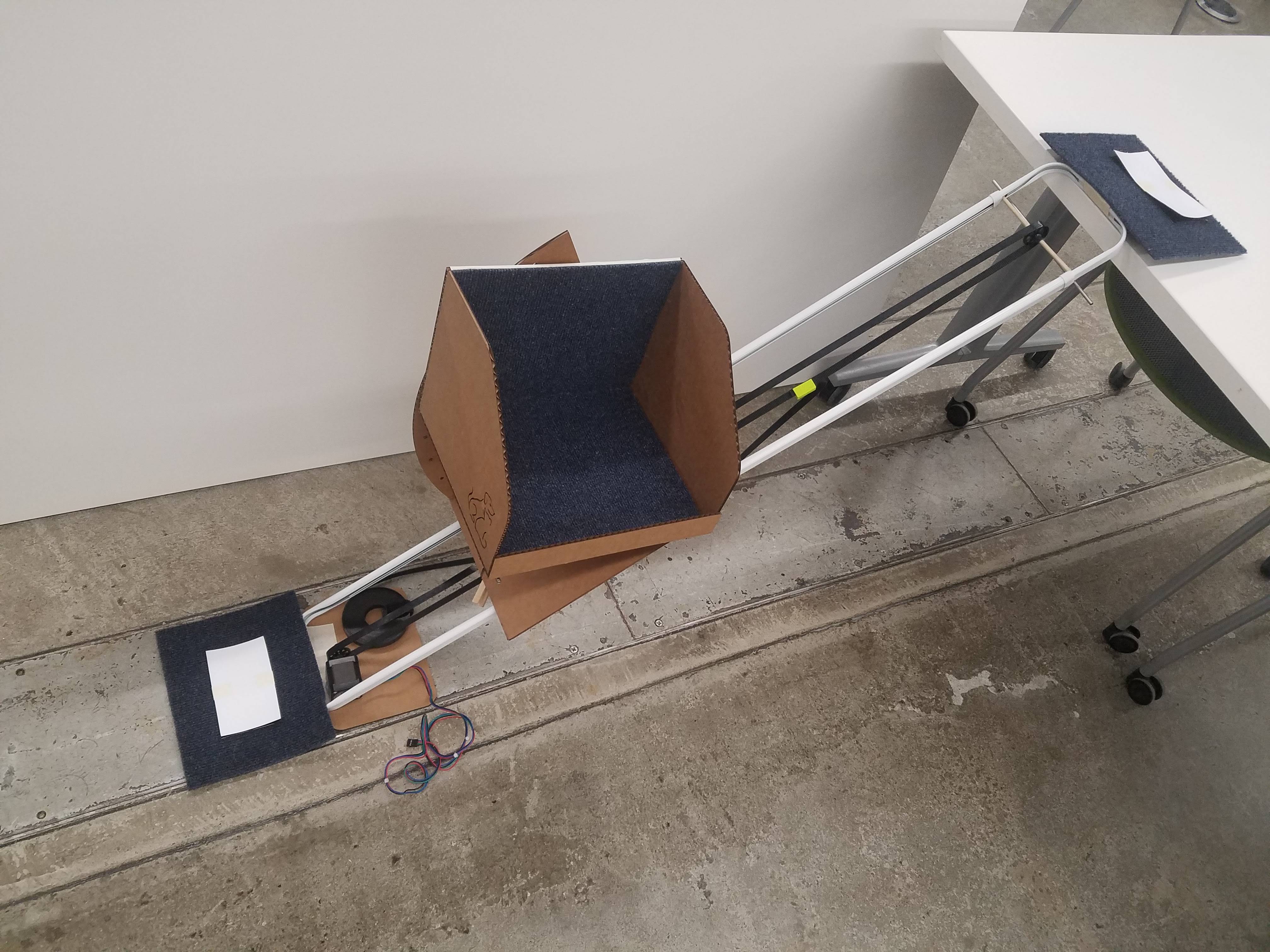
I originally intended to attach the curtain rods using a block of wood on either end. I was thinking of attaching hinges to these wood blocks so that I could attach two other wooden pieces that could support the frame and prevent it from sliding out under its own weight. However, I had used the small laser cut pieces instead to join the frame and decided against drilling into the curtain rods to attach heavy supports directly. So, instead, I used cardboard pieces and masking tape. Similar to how I used masking tape to create a makeshift hinge connecting the carriage to the angle adjustment mechanism, I used masking tape here to connect the carboard "supports" to the frame, as pictured below. One of the other reasons I decided to go with cardboard was that I wanted to use pressure sensors that ideally would be concealed under the supports and using heavy wood instead of cardboard may have made it difficult because of how sensitive the sensors are (more on these to come).
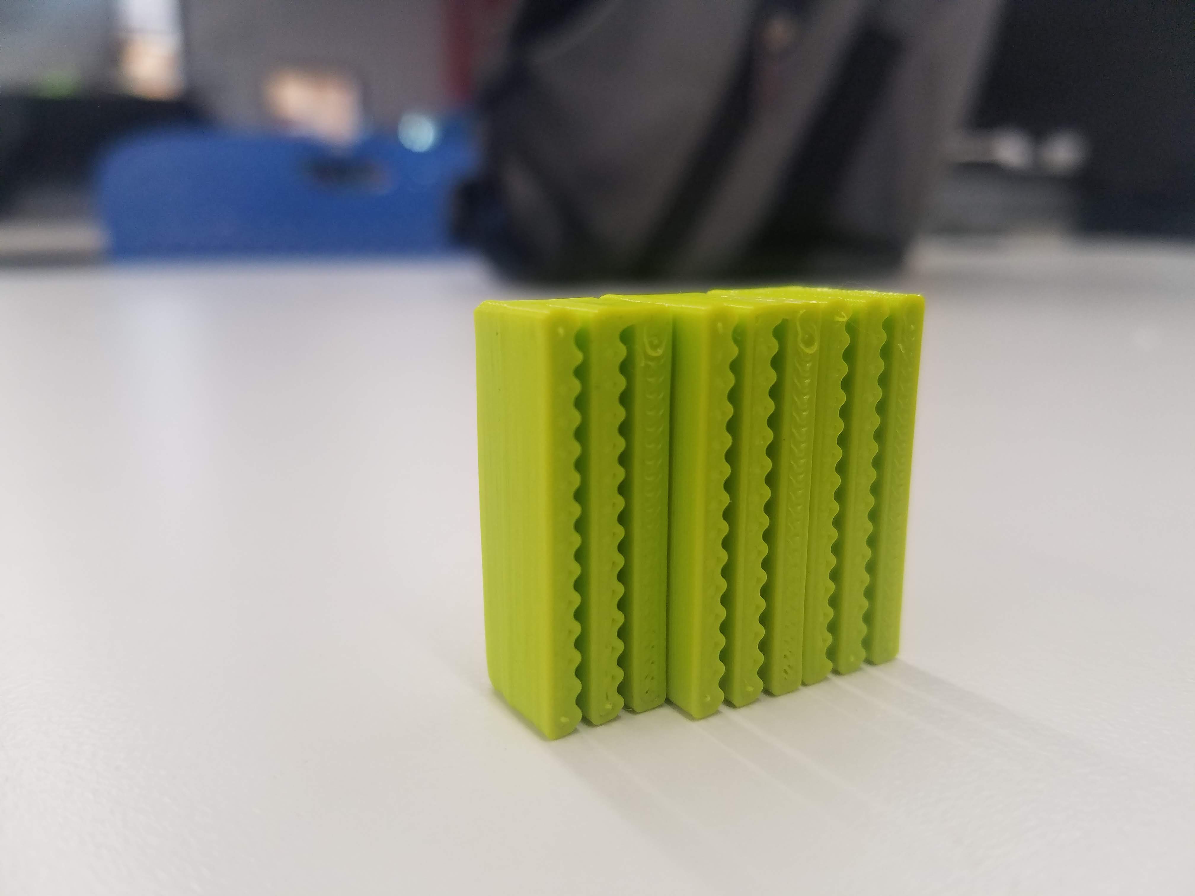
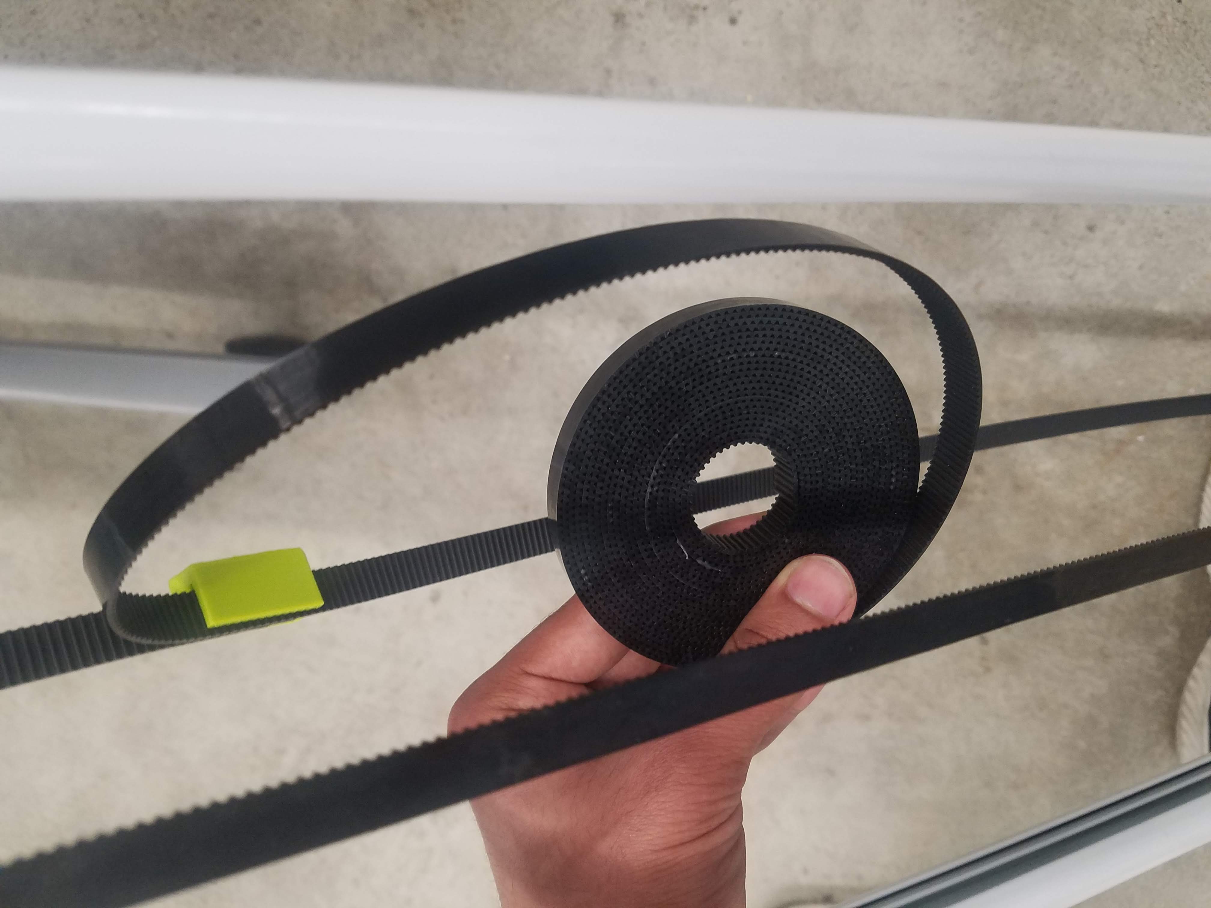
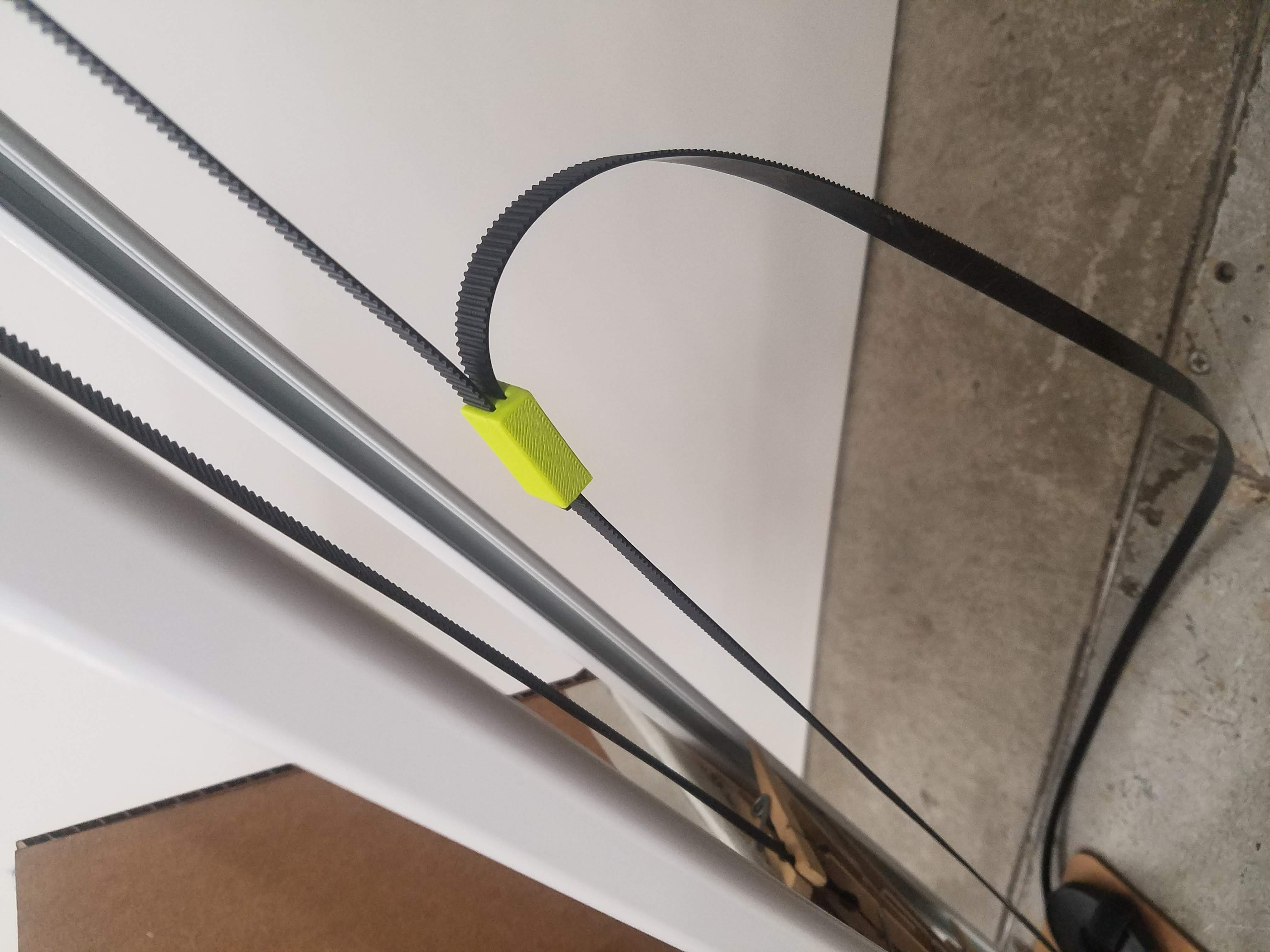
Next, I focused on how to make the length of the timing belt adjustable. I thought of many ideas and experimented with them, for example just using a small binder clip, but ultimately decided to go with a 3D-printed part that held onto the timing belt at either end of the loop very tightly. I designed this part in Fusion 360 by following a tutorial on YouTube describing how to model a simple timing belt in Fusion 360 and referencing this image. I did not follow the tutorial in its entirety (because I was not looking to model a closed-loop timing belt) but used it as a starting point and borrowed some ideas that proved to be very helpful. I had to 3D print this part three times in total because the first time, the gaps between levels were too narrow for the timing belt to fit and they were not wide enough. The second time, I got a satisfactory result but realized that it would be significantly easier if I removed one component so that the belt from either side of the loop could slot into the part. And the third time was the charm for sure! (I later tried to recycle these "failed attempts" to keep the timing belt from slipping off the gear although that turned out not to be very effective.) Also, this seemingly small part is the one thing I am most happy about from this build.
2nd iteration:
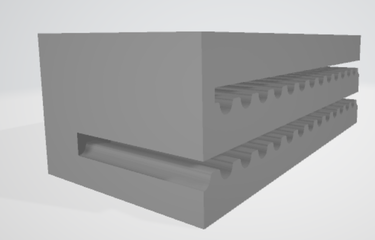
3rd iteration:
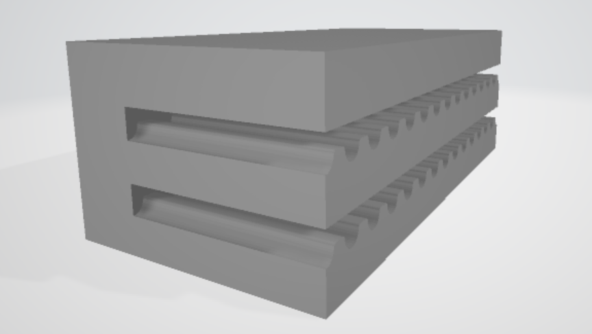
Three iterations side by side:
Keeping the timing belt tight:
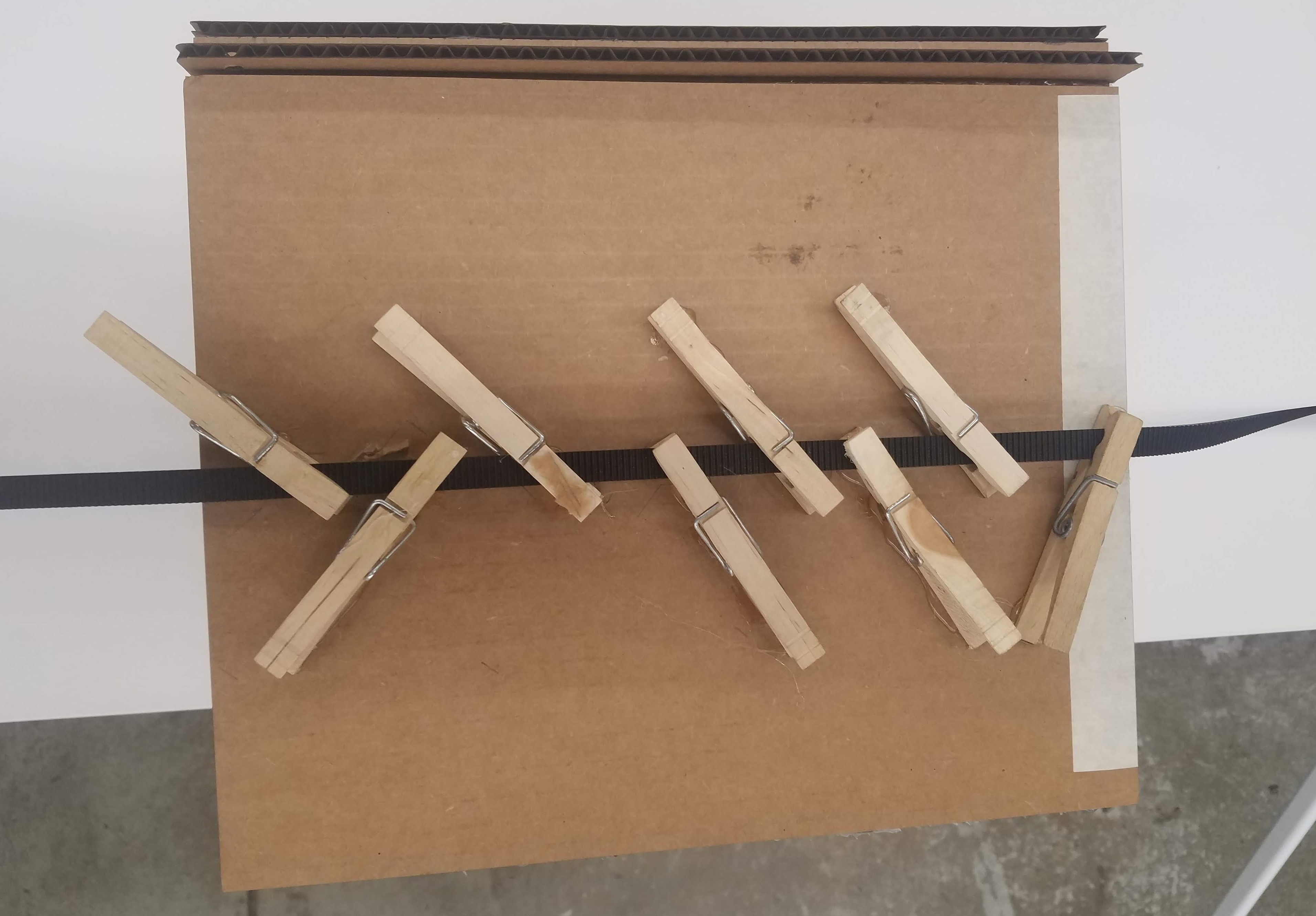
The frame with the timing belt and the carriage with the angle adjustment mechanism were separate at this point in the build and I wanted to bring them together. I ultimately decided to use clothespins to do this. I hot glued the clothespins to the bottom of the baseplate of the angle adjustment mechanism such that they could all latch onto the timing belt and secure the carriage in place. This worked surprisingly well, and I was happy with the results, because it was difficult to decide what angles each pin should be at and which direction they should face.
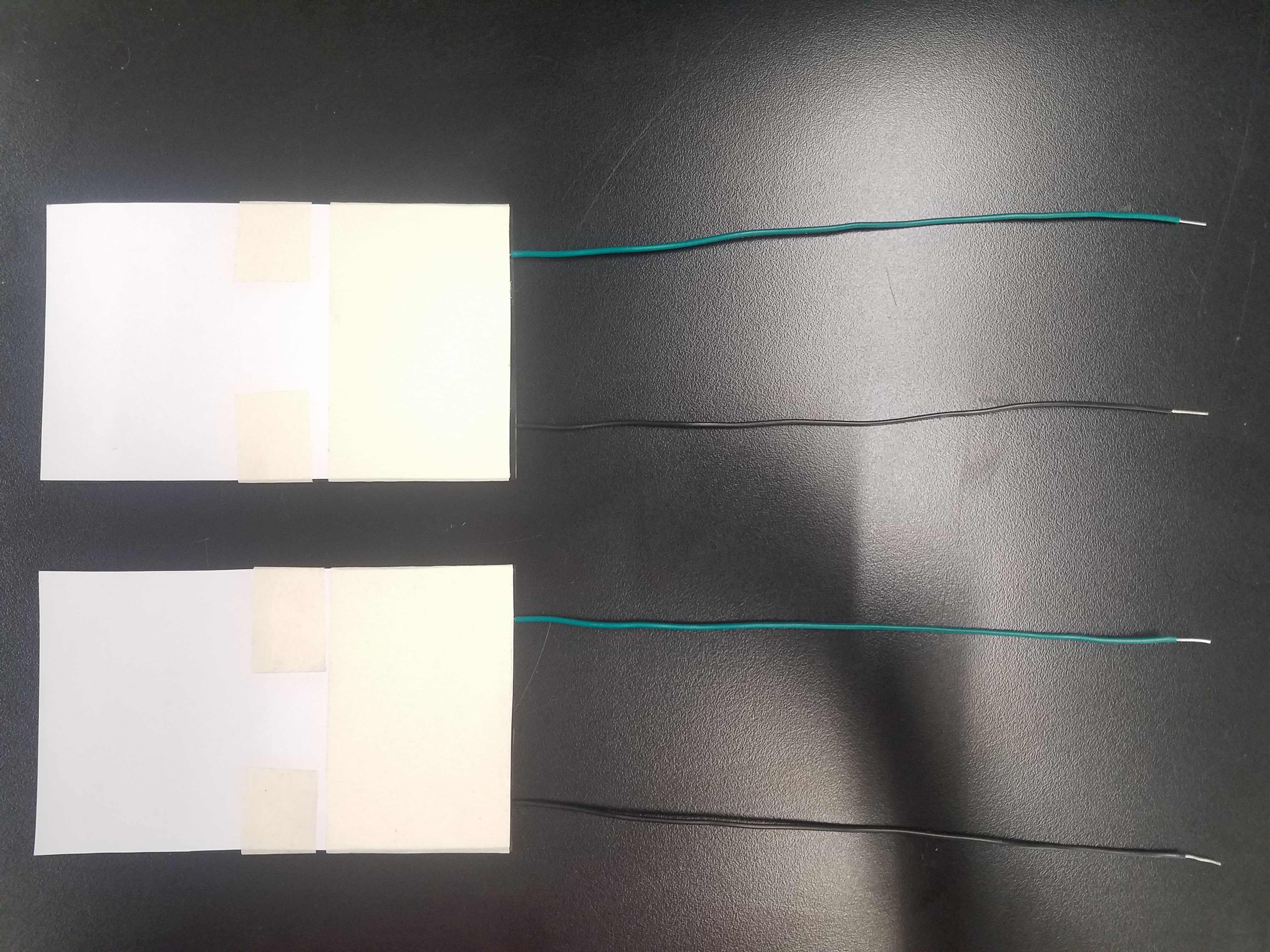
At this point, I made the pressure sensors by sandwiching a layer of velostat between two copper foil rectangles, taking care that the copper rectangles were not touching. I stuck leads onto the sticky side of the copper foil rectangles and spent two hours trying to figure out why the serial monitor was not giving consistent results. I later realized that the sticky side of the copper rectangles are non-conductive. Once I switched the side of the copper stickers the leads were placed, I got really consistent results and gained an appreciation for just how sensitive they were to changes in pressure.
The pressure sensors:
Wire setup:
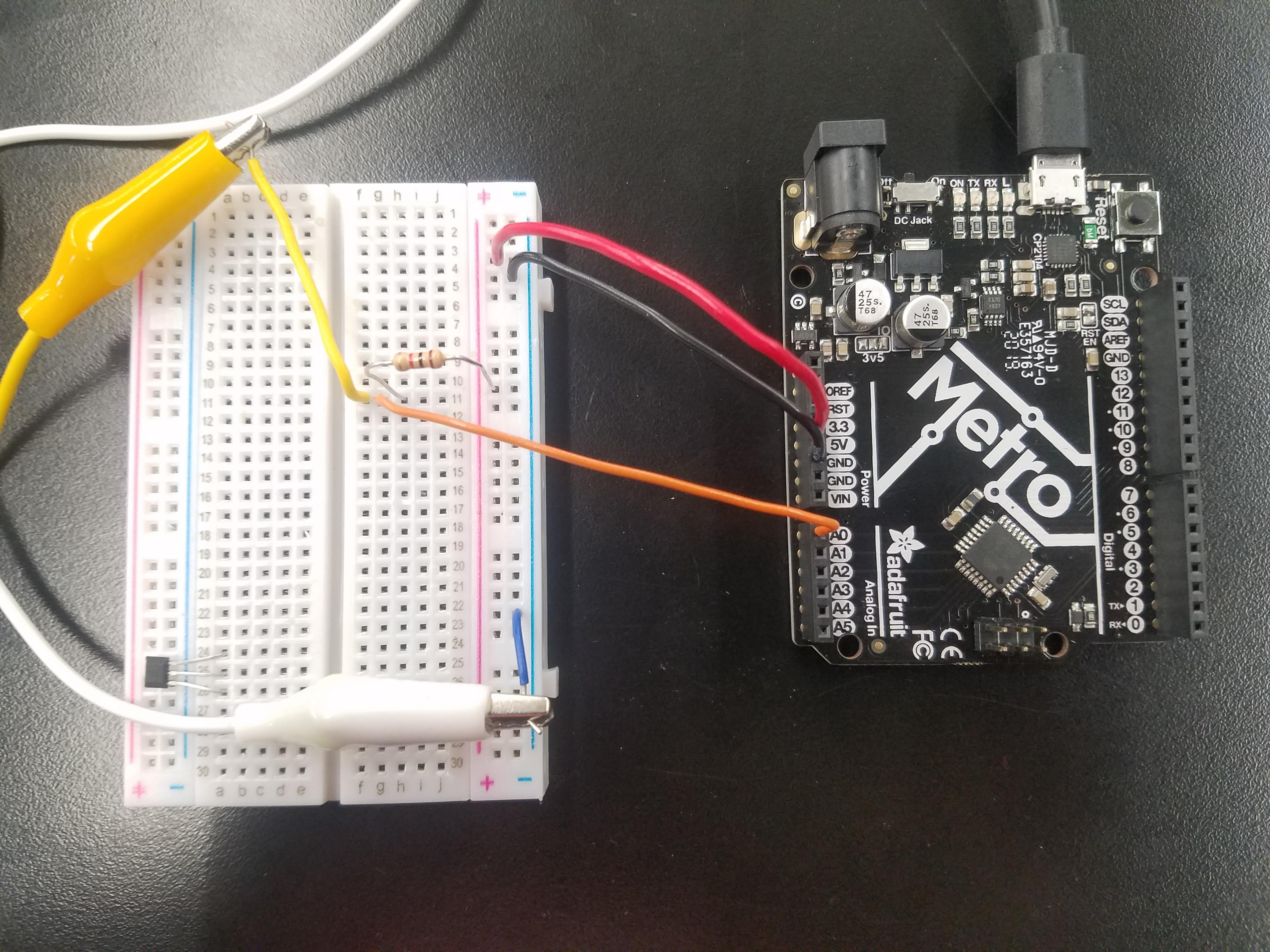
Serial plotter readings:
Now, I was in a position where I could start putting everything together. I cut squares of carpet to decorate the inside of the carriage and to cover the cardboard supports (using double-sided sticky tape), under which the pressure sensors would go. I also glued the stepper motor to another cardboard support I added at the foot of, and underneath, the frame. Here are some photos from the first time I put the physical components of the project together:
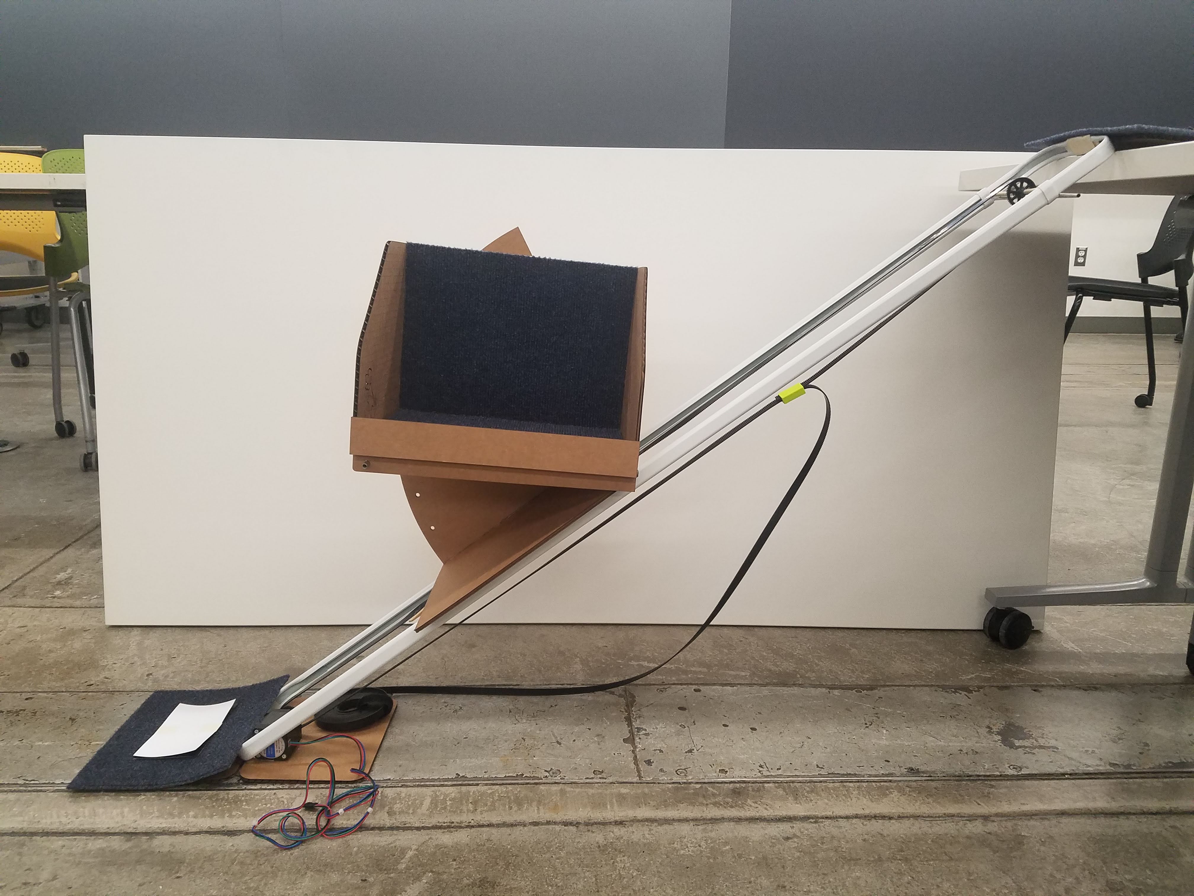
Project Documentation: Electronics
The goals of the project in terms of how I wanted it to function are described in the demo video. I do not have a background in computer science or programming, so I went into the coding process blindly. I borrowed, drew inspiration from, and modified aspects of the code from the Week 10 assignment because of how similar the outcomes are to what we want in this project. I had been thinking about using magnetic hall sensors to control where the elevator stops on the frame since week six, but it was not until week 10 that I really had a chance to experiment with different outcomes depending on inputs from hall sensors.
Here is the initial program I tested. Majority of it is actually code I wrote after reading through several forums and asking silly questions on Google, for example the ways in which while and if statements are different. The homing sequence is taken directly from the week 10 project, however. I used digitalRead() a lot because the tutorial I followed for the week 10 assignment did.
        // Define connections
        #define DIR               10
        #define STEP              11
        #define Hall_sensor_top   2
        #define Hall_sensor_bot   3
        int Touch_sensor_top   =  A0;
        int Touch_sensor_bot   =  A1;


        void homefunction() {
          // Set motor speed pulse duration
          int pd = 4000;

          // Move motor until home position reached
            digitalWrite(DIR, LOW);
            delay(1000);
            while (digitalRead(Hall_sensor_bot) == 1) {
            digitalWrite(STEP, HIGH);
            delayMicroseconds(pd);
            digitalWrite(STEP, LOW);
            delayMicroseconds(pd);
          }
        }

        void setup() {
          Serial.begin(9600);
          // Setup the stepper controller pins as outputs
          pinMode(DIR, OUTPUT);
          pinMode(STEP, OUTPUT);

          // Setup the hall effect sensors as an input
          pinMode(Hall_sensor_top, INPUT);
          pinMode(Hall_sensor_bot, INPUT);

          // Setup the touch sensors as inputs
          pinMode(Touch_sensor_top, INPUT);
          pinMode(Touch_sensor_bot, INPUT);

          // Home the motor
          homefunction();

        }

        void loop()  {

          //If the bottom touch sensor is activated, and the top hall sensor is activated or the bottom hall sensor is not activated...

          if (digitalRead(Touch_sensor_bot) == 1 && (digitalRead(Hall_sensor_top) == 1) || (digitalRead(Hall_sensor_bot == 0))) {

            //Move down
            while (digitalRead(Hall_sensor_bot) == 0) {
              digitalWrite(DIR, LOW); //Figure out direction
              digitalWrite(STEP, HIGH);
              delayMicroseconds(4000);
              digitalWrite(STEP, LOW);
              delayMicroseconds(4000);
            }


            if (digitalRead(Hall_sensor_bot == 1)) {
              //Time to get on elevator
              delay(5000);

              //Moving up
              while (digitalRead(Hall_sensor_top == 0)) {
                digitalWrite(DIR, HIGH); //Figure out direction. Reverse of before
                digitalWrite(STEP, HIGH);
                delayMicroseconds(4000);
                digitalWrite(STEP, LOW);
                delayMicroseconds(4000);
              }

              //Time to get off elevator
              delay(5000);

              digitalWrite(Hall_sensor_top, 0);
            }
          }

          //If the top touch sensor is activated, and the bottom hall sensor is activated or the top hall sensor is not activated...

          if (digitalRead(Touch_sensor_top) == 1 && (digitalRead(Hall_sensor_bot) == 1) || (digitalRead(Hall_sensor_top == 0))) {

            //Move up
            while (digitalRead(Hall_sensor_top == 0)) {
              digitalWrite(DIR, HIGH); //Figure out direction
              digitalWrite(STEP, HIGH);
              delayMicroseconds(4000);
              digitalWrite(STEP, LOW);
              delayMicroseconds(4000);
            }


             //Time to get on elevator
             if (digitalRead(Hall_sensor_top == 1)) {
             delay(5000);

            //Moving down
            while (digitalRead(Hall_sensor_top == 0)) {
            digitalWrite(DIR, LOW); //Figure out direction. Reverse of before
            digitalWrite(STEP, HIGH);
            delayMicroseconds(4000);
            digitalWrite(STEP, LOW);
            delayMicroseconds(4000);
            }

             //Time to get off elevator
             delay(5000);

              digitalWrite(Hall_sensor_top, 0);
            }
          }
        }
I did all the troubleshooting while the carriage and timing belt were not connected to the servo for convenience. I was having a lot of difficulty figuring out what the issue was in my code, however, and after speaking to Professor Melenbrink about it, I decided to change the inputs from the hall and pressure sensors to analogRead() instead of digitalRead(). I calibrated the sensors quickly by running the following code:
          // the setup routine runs once when you press reset:
          void setup() {
          // initialize serial communication at 9600 bits per second:
          Serial.begin(9600);
          }

          // the loop routine runs over and over again forever:
          void loop() {
            // read the input on analog pin 0:
            int sensorValue = analogRead(A0);
            // print out the value you read:
            Serial.println(sensorValue);
            delay(10);        // delay in between reads for stability
          }
Based on the results of using analog read serial, I went with about 70 as the cutoff for the bottom pressure sensor, about 100 for the top pressure sensor, and 530 for both magnetic hall sensors. I also incorporated Serial.println() statements into each of the while loops in the code to determine which loop the program was stuck in. At first, it kept saying that it was stuck in while loop 2, so I changed the parameters and removed the && and || statements, and as I kept doing that for each while loop, I noticed that eventually the motor stopped getting stuck immediately after the homing sequence was over. Instead, I noticed that every time I touched the bottom sensor, it would enter into a while loop until I stopped applying pressure on the sensor. Perhaps more interestingly, it would cycle from being stuck in loop one to being stuck in loop two, to being stuck in loop three, and so on. All the input sensors were working fine, but the program could not seem to be able to parse my code.
I asked for help from several of my peers, but eventually gave up because the debugging process could have easily taken up several more hours. Here is what my code looked like (when I opted to use the code from week 10 to keep the elevator moving constantly from top to bottom):
          // Define connections
          #define DIR              10
          #define STEP             11
          int Touch_sensor_bot = analogRead(A0);
          int Touch_sensor_top = analogRead(A1);
          int Hall_sensor_bot = analogRead(A2);
          int Hall_sensor_top = analogRead(A3);

          void homefunction() {
            // Set motor speed pulse duration
            int pd = 4000;

            // Move motor until home position reached
            delay(1000);
            digitalWrite(DIR, LOW);


            while (analogRead(Hall_sensor_bot) < 530) {
              digitalWrite(STEP, HIGH);
              delayMicroseconds(pd);
              digitalWrite(STEP, LOW);
              delayMicroseconds(pd);
              Serial.println("Homing");
            }
          }


          void setup() {
            Serial.begin(9600);
            // Setup the stepper controller pins as outputs
            pinMode(DIR, OUTPUT);
            pinMode(STEP, OUTPUT);

            // Setup the hall effect sensors as an input
            pinMode(Hall_sensor_top, INPUT);
            pinMode(Hall_sensor_bot, INPUT);

            // Setup the touch sensors as inputs
            pinMode(Touch_sensor_top, INPUT);
            pinMode(Touch_sensor_bot, INPUT);

            // Home the motor
          //  homefunction();
          }


          void loop()  {

           if (analogRead(Touch_sensor_bot) < 100) {

            Serial.println("Touch sensor bot");

              //Move down
              while (analogRead(Hall_sensor_bot) < 530) {
                digitalWrite(DIR, LOW); //Figure out direction
                digitalWrite(STEP, HIGH);
                delayMicroseconds(4000);
                digitalWrite(STEP, LOW);
                delayMicroseconds(4000);
                //Serial.println("In while loop 1");

                  //Time to get on elevator
                  if (analogRead(Hall_sensor_bot) > 530) {
                    delay(5000);
                  }
              }

                //Moving up
                while (analogRead(Hall_sensor_top) < 530) {
                  digitalWrite(DIR, HIGH); //Figure out direction. Reverse of before
                  digitalWrite(STEP, HIGH);
                  delayMicroseconds(4000);
                  digitalWrite(STEP, LOW);
                  delayMicroseconds(4000);
                  //Serial.println("In while loop 2");
                }

                //Time to get off elevator
                delay(5000);
              }


            if (analogRead(Touch_sensor_top) < 100) {

                Serial.println("Touch sensor top");

              //Move up
              while (analogRead(Hall_sensor_top ) < 530) {
                digitalWrite(DIR, HIGH); //Figure out direction
                digitalWrite(STEP, HIGH);
                delayMicroseconds(4000);
                digitalWrite(STEP, LOW);
                delayMicroseconds(4000);
                //Serial.println("In while loop 3");
                //Serial.println(analogRead(Hall_sensor_top));
              }

              //Time to get on elevator
              if (analogRead(Hall_sensor_top )> 530) {
                delay(5000);

                //Moving down
                while (analogRead(Hall_sensor_bot ) < 530) {
                  digitalWrite(DIR, LOW); //Figure out direction. Reverse of before
                  digitalWrite(STEP, HIGH);
                  delayMicroseconds(4000);
                  digitalWrite(STEP, LOW);
                  delayMicroseconds(4000);
                  //Serial.println("In while loop 4");
                  //Serial.println(analogRead(Hall_sensor_bot));
                }

                //Time to get off elevator
                delay(5000);
              }
            }
            }
It was strange because sometimes the program only recognized one of the sensors, even though it kept getting the two mixed up in serial monitor. I could have been touching the bottom pressure sensor, for example, and it would identify it as the top sensor occasionally instead. So, I decided to leave the touch sensors out of the equation and upload a program that I knew worked. Here is the code from week 10 I decided to use:
       /*
         Stepper Motor Limit Switch Demo
         stepper-limit-demo.ino
         Uses Hall Effect sensors as limit switches
         Uses A4988 Stepper Motor Driver module

         DroneBot Workshop 2019
         https://dronebotworkshop.com
       */

       // Define connections
       #define HALL_SENSOR_A      2
       #define HALL_SENSOR_B      3
       #define DIR      10
       #define STEP      11

       // Variables
       int pd = 4000;       // Pulse Delay period
       boolean setdir = LOW; // Set Direction

       // Interrupt Handlers

       void limit_a (){

         // Reverse motor
         setdir = !setdir;

       }

       void limit_b (){

         // Reverse motor
         setdir = !setdir;

       }


       void setup() {

         // Setup the stepper controller pins as Outputs
         pinMode(DIR,OUTPUT);
         pinMode(STEP,OUTPUT);

         // Setup the Hall Effect switches as Inputs
         pinMode(HALL_SENSOR_A, INPUT);
         pinMode(HALL_SENSOR_B, INPUT);

         // Attach interrupt pins to handlers
         attachInterrupt(digitalPinToInterrupt(HALL_SENSOR_A), limit_a, FALLING);
         attachInterrupt(digitalPinToInterrupt(HALL_SENSOR_B), limit_b, FALLING);

       }

       void loop() {

           digitalWrite(DIR,setdir);
           digitalWrite(STEP,HIGH);
           delayMicroseconds(pd);
           digitalWrite(STEP,LOW);
           delayMicroseconds(pd);

       }
After I uploaded the code to my microcontroller, I quickly realized that the stepper motor could not handle the load of the carriage and it was acting very strangely. A counterweight would have helped in ths regard. Also, one of the magnetic hall sensors that I had soldered (the one with wires extending to the top) started smoking and got fried as well. At that point, I knew the project would not be functional by the deadline but I was really happy with at least the fabrication aspect, even if the digital aspect did not quite work out.
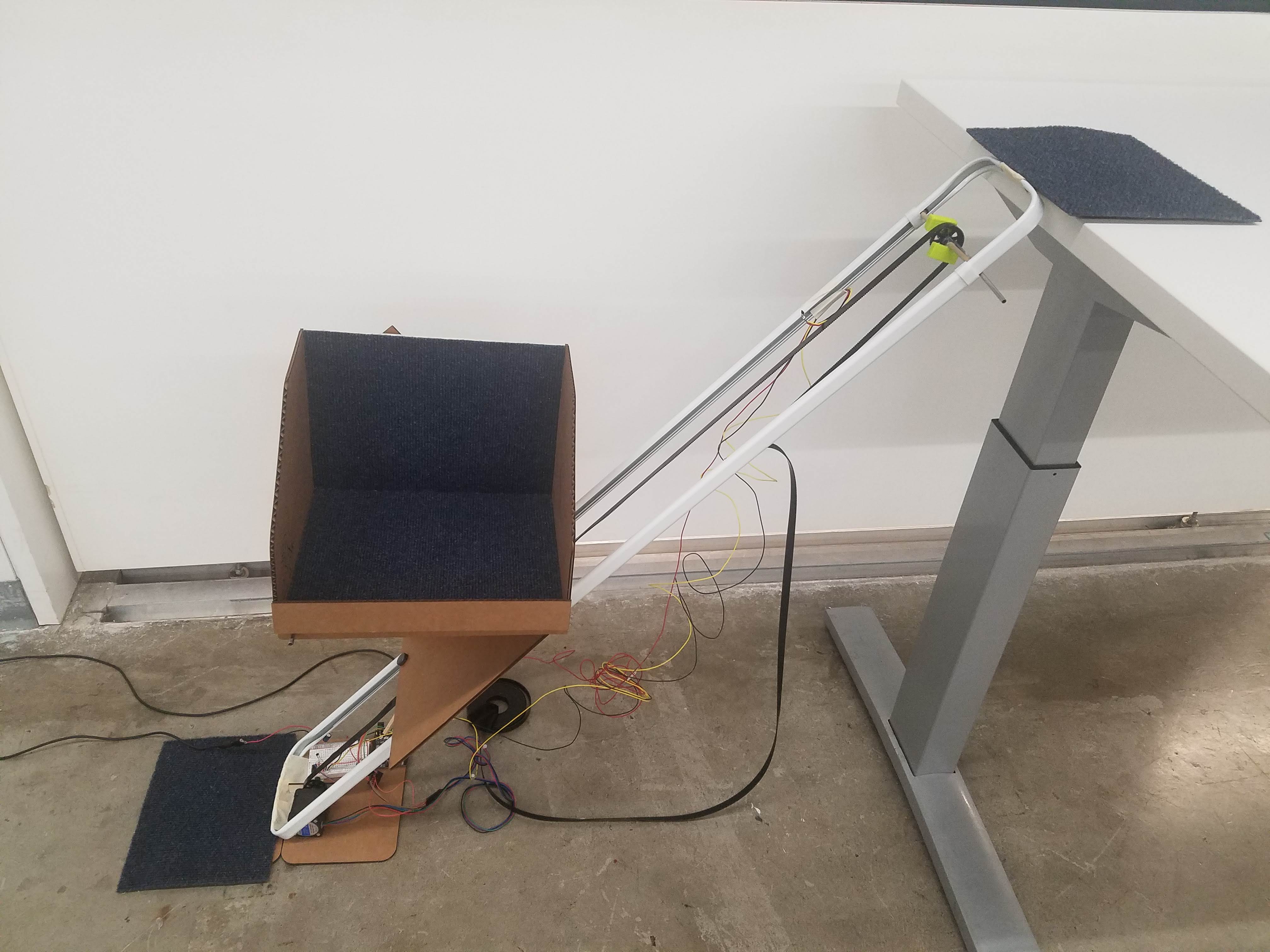
Although I do not have a video of my project working, here are some final pictures with everything complete, including wiring and placement of magnetic hall sensors and magnets.
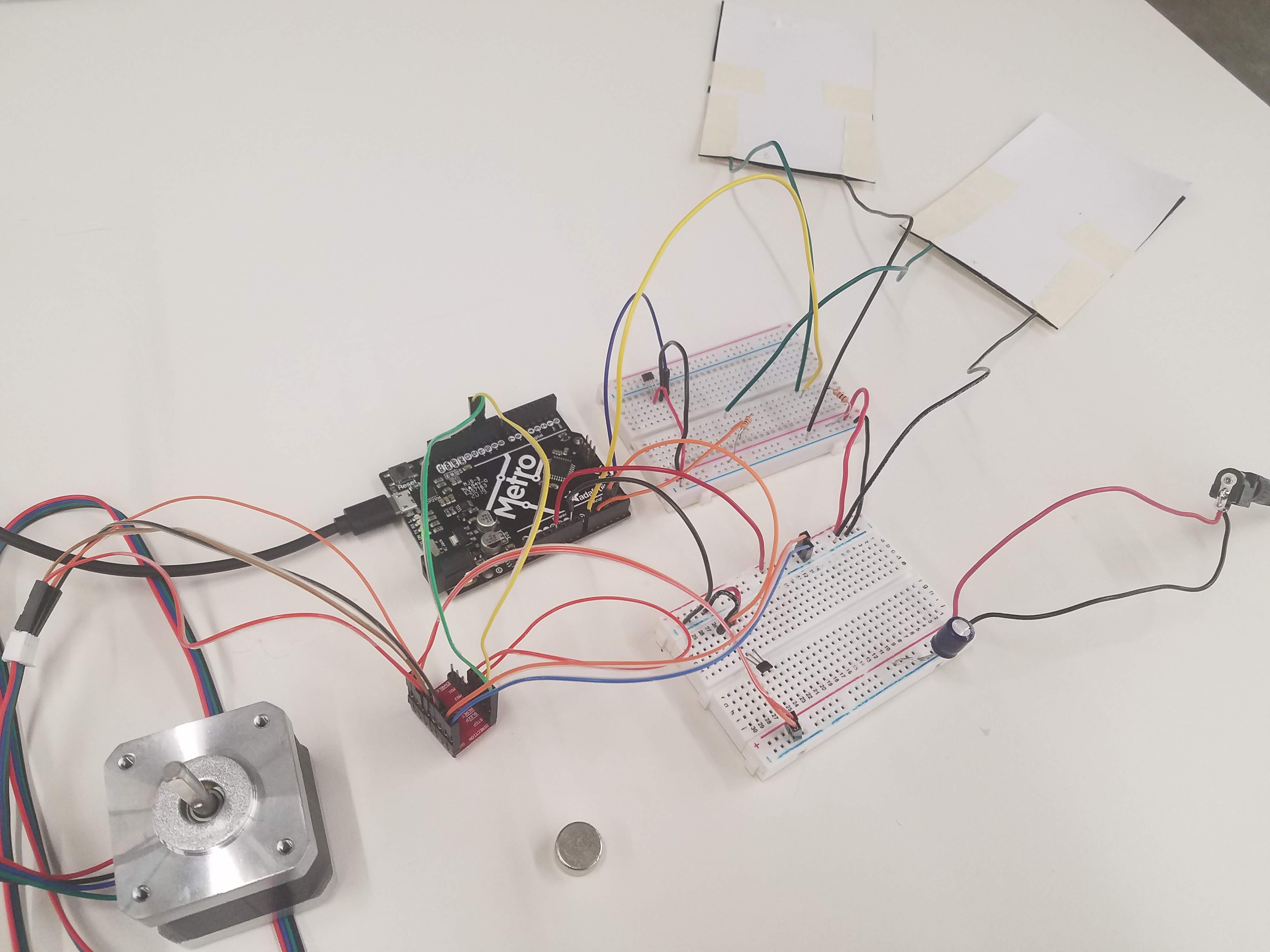
Wiring setup while testing individual components:
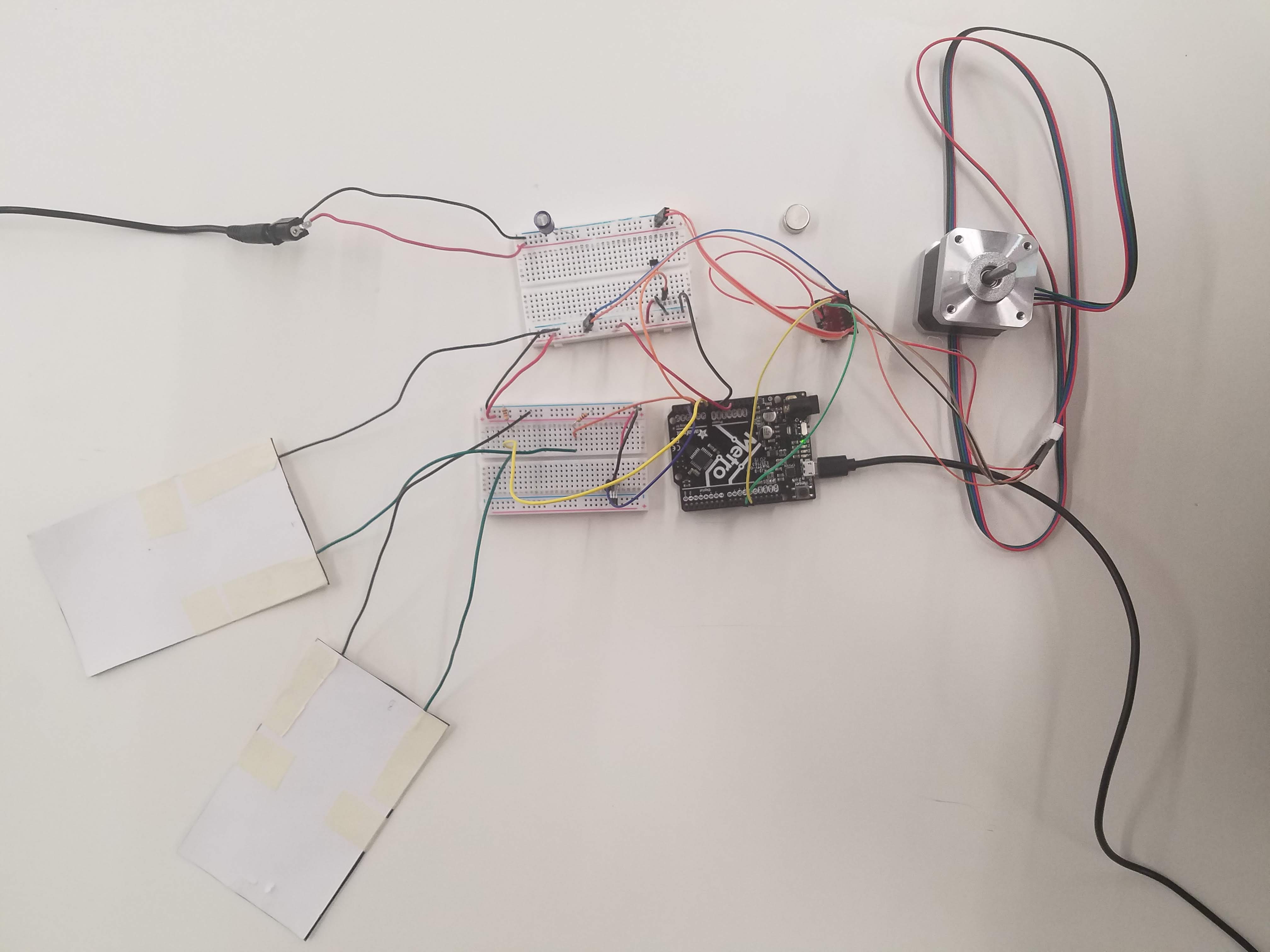
All wired up:
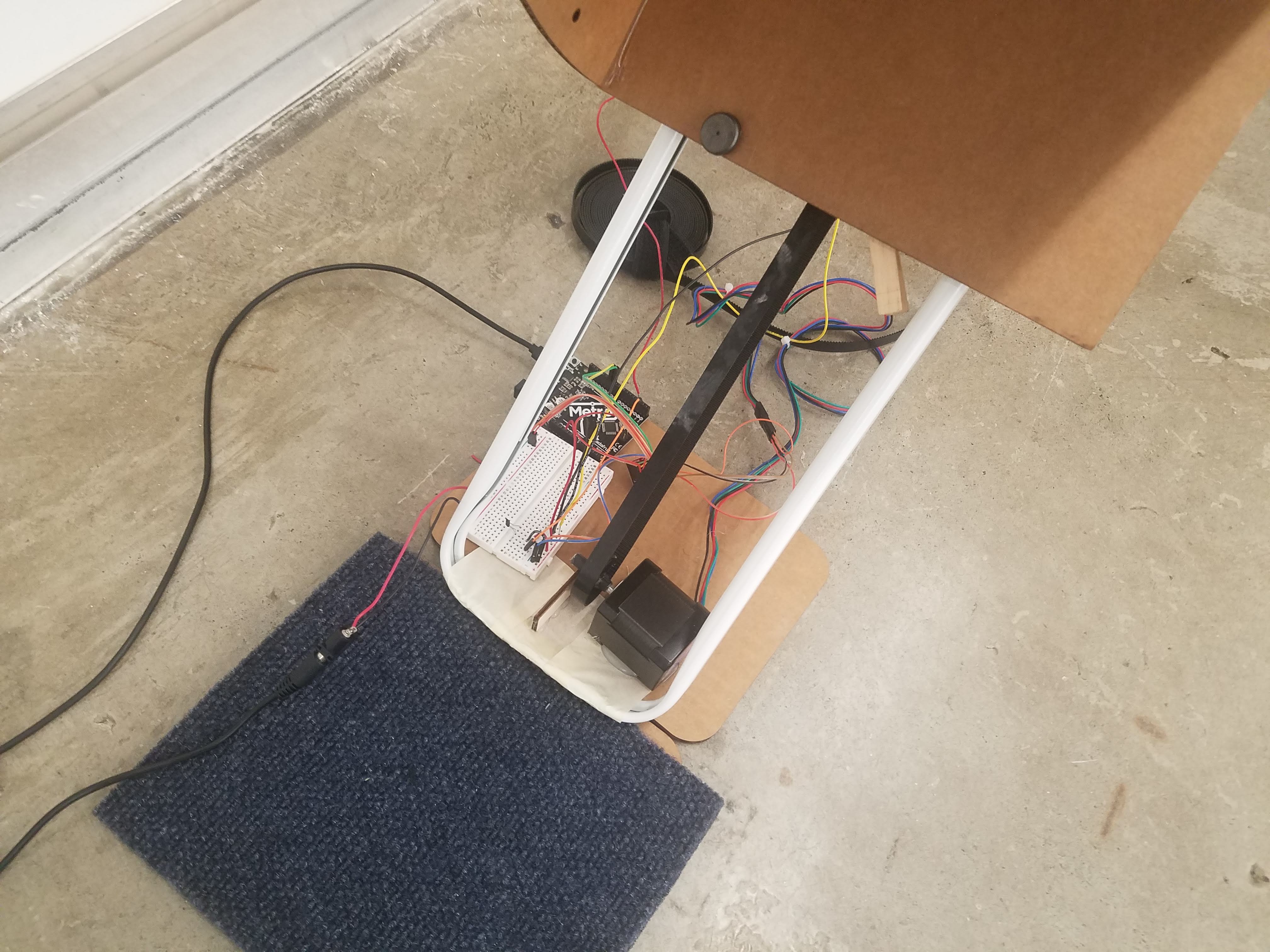
Files for download
Curtain rod connectors and supports
Resources
https://dronebotworkshop.com/stepper-motor-hall-effect/
https://www.homedepot.com/p/48-in-84-in-Single-Curtain-Rod-in-White-869473/309976499
https://www.instructables.com/Velostat-Homemade-Pressure-Sensor-Mat/
https://nathanmelenbrink.github.io/ps70/
https://www.robotics.org.za/image/catalog/generic/GT2-6MM/GT2-6MM%20-%20Layout02.jpg
http://www.uwyo.edu/esp4t/arduino-modules/data-measurement-modules/pressure-sensor.html
Special thanks to the wonderful teaching staff that make PHYSCI 70 possible!Powered by w3.css
Mohammed Mutaher 2022