Week 10: Machine Building and End Effectors
This week, we focused on machine learning and end effectors.
We were tasked with building a simple machine using at least a stepper motor, commanding the machine to get repeatable results, and calibrating motor position. I completed the assignment by following the tutorial linked here on dronebotworkshop.com. Documentation for the project, divided into two parts, is provided below.
Part 1: Calibrating Stepper Motor Position Using a Hall Effect Sensor
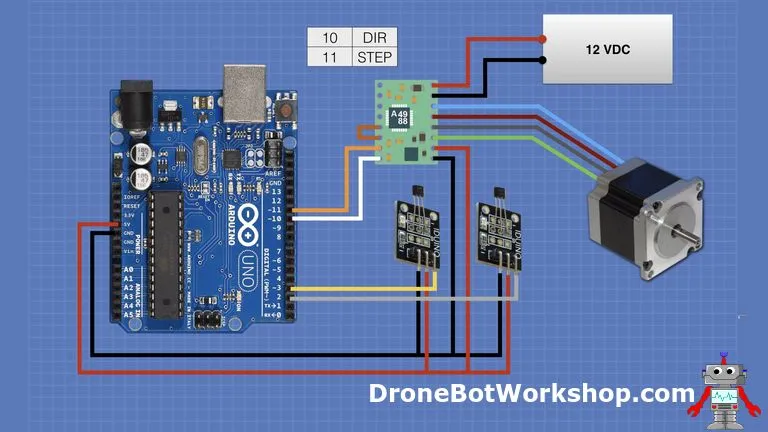
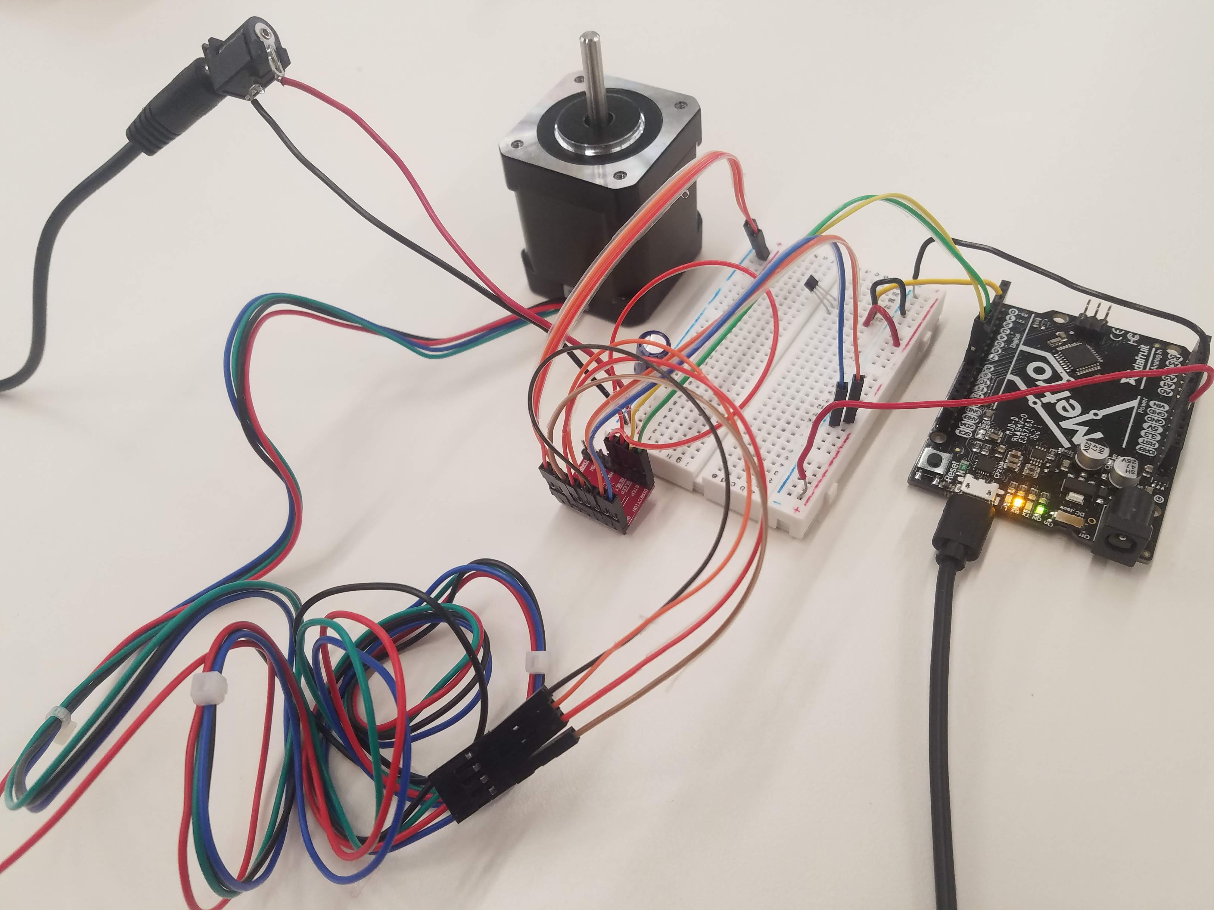
Following the tutorial linked above, I was able to calibrate motor position using a homing sequence that guarantees the "home" position is the same every time the device is powered on or restarted. I followed the schematic shown below to complete the wiring setup.
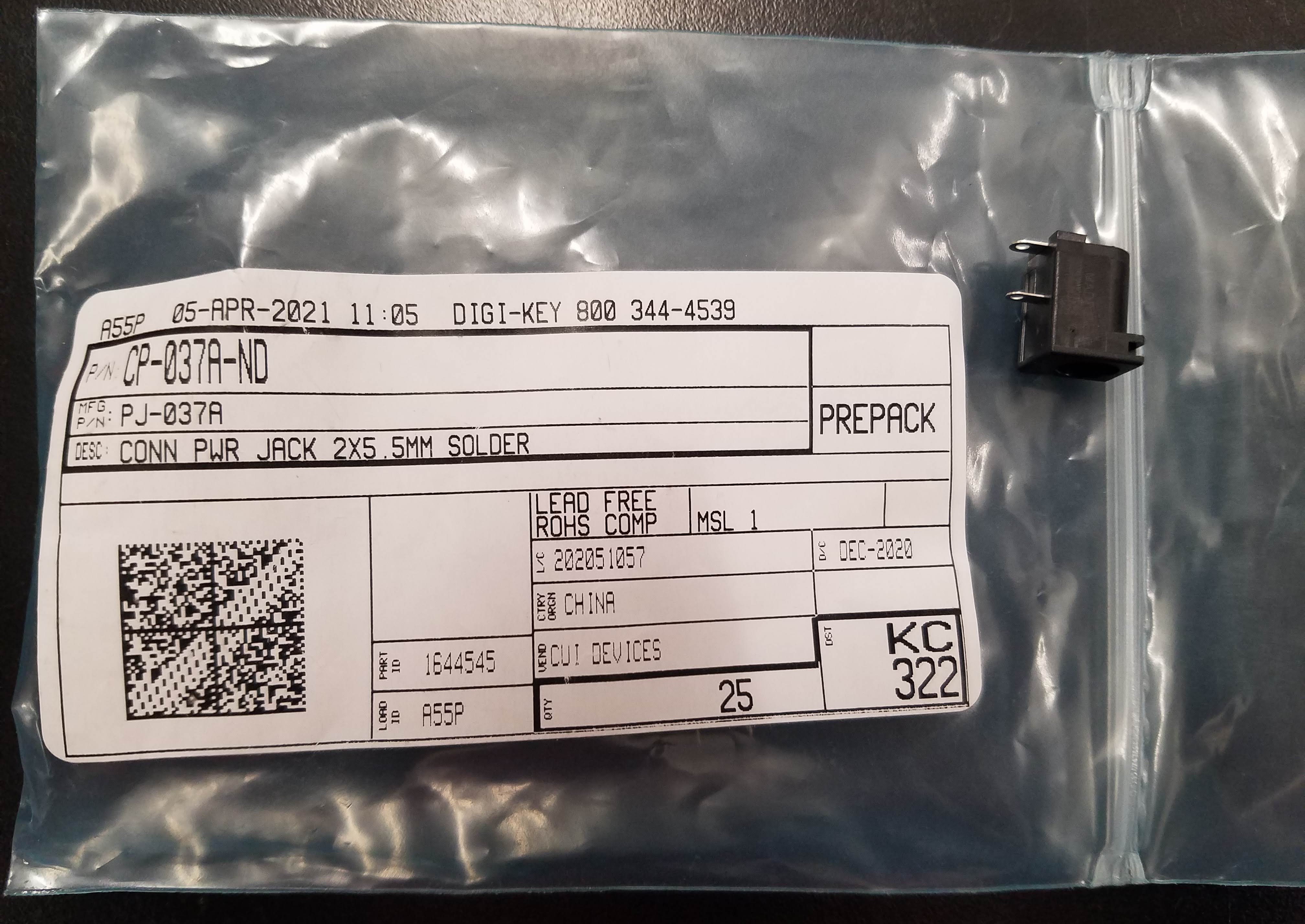
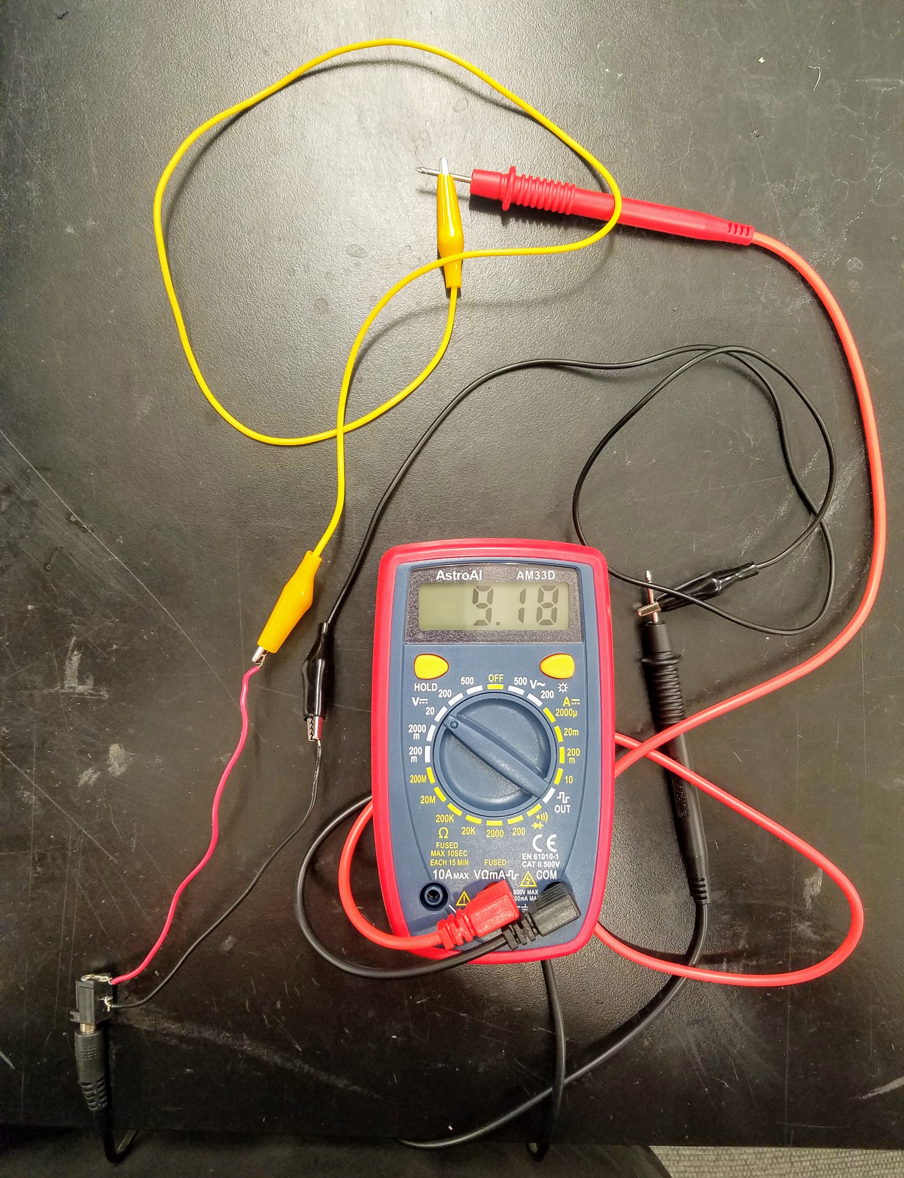
I used a 9V DC power supply instead of a 12V DC power supply. To power the breadboard using this adapter, I attached a power jack and soldered wires onto the leads. Then, to ensure that it was working as intended, I plugged the adapter into a wall socket and used a voltmeter to measure the output as shown in the pictures below.
Adapting the 9V DC power supply for the breadboard:
Additionally, this part of the project only requires the magnetic hall sensor attached to pin 3. As such, I did not connect the second magnetic hall sensor attached to pin 2 until I moved on to the second part of the project (which involves using both sensors). Also, an A4988 stepper motor driver was used.
Wire setup:
The code is as follows:
        /*
          Stepper Motor Homing Switch Demo
          stepper-homing-demo.ino
          Uses Hall Effect sensor as homing switch
          Uses A4988 Stepper Motor Driver module

          DroneBot Workshop 2019
          https://dronebotworkshop.com
        */

        // Define connections
        #define HALL_SENSOR      3
        #define DIR      10
        #define STEP      11

        // Direction Variable
        boolean setdir = LOW;

        void homefunction() {
          // Set motor speed pulse duration
          int pd = 4000;

          // Move motor until home position reached
          while (digitalRead(HALL_SENSOR) == 1) {

            digitalWrite(DIR, setdir);
            digitalWrite(STEP, HIGH);
            delayMicroseconds(pd);
            digitalWrite(STEP, LOW);
            delayMicroseconds(pd);
          }

        }

        void setup() {

          // Setup the stepper controller pins as Outputs
          pinMode(DIR, OUTPUT);
          pinMode(STEP, OUTPUT);

          // Setup the Hall Effect switch as an Input
          pinMode(HALL_SENSOR, INPUT);

          // Home the motor
          homefunction();

        }

        void loop() {

          // Loop, put code here

        }
I modified the original code above to include "Serial.begin(9600);" under void setup(){} and "Serial.println(digitalRead(HALL_SENSOR));" under void loop(){} because I needed to troubleshoot. As it turned out, I had mixed up the power and ground pins on the magnetic hall sensor so it was not working as intended at first. (Note: The pictures of the wiring setup above were taken after I corrected the wiring.) I also moved the "homefunction();" command from void setup(){} to void loop(){} so that I could experiment with the magnetic hall sensor and better understand how it works in the hopes of using it as potential mechanism to control my final project. For more information about the code, visit the tutorial linked here
again.And here it is in action, with the modifications I made to the code. I attached a piece of tape to the shaft of the stepper motor to make its rotation easier to see:
Note that by reversing the poles of the magnet, I can get the motor to start and stop. While this particular functionality would not be very useful in the context of my final project, I found it really interesting! I also realized that if I used the original code with "homefunction();"" inside of void setup(){} versus void loop(){}, I could use it to calibrate the position of the stepper motor in my final project. The motor would continue rotating until the magnetic hall sensor detected the magnet, stop, and then execute the code in void loop(){}.
Part 2: Making a Simple Machine Using Two Magnetic Hall Sensors and a Stepper Motor
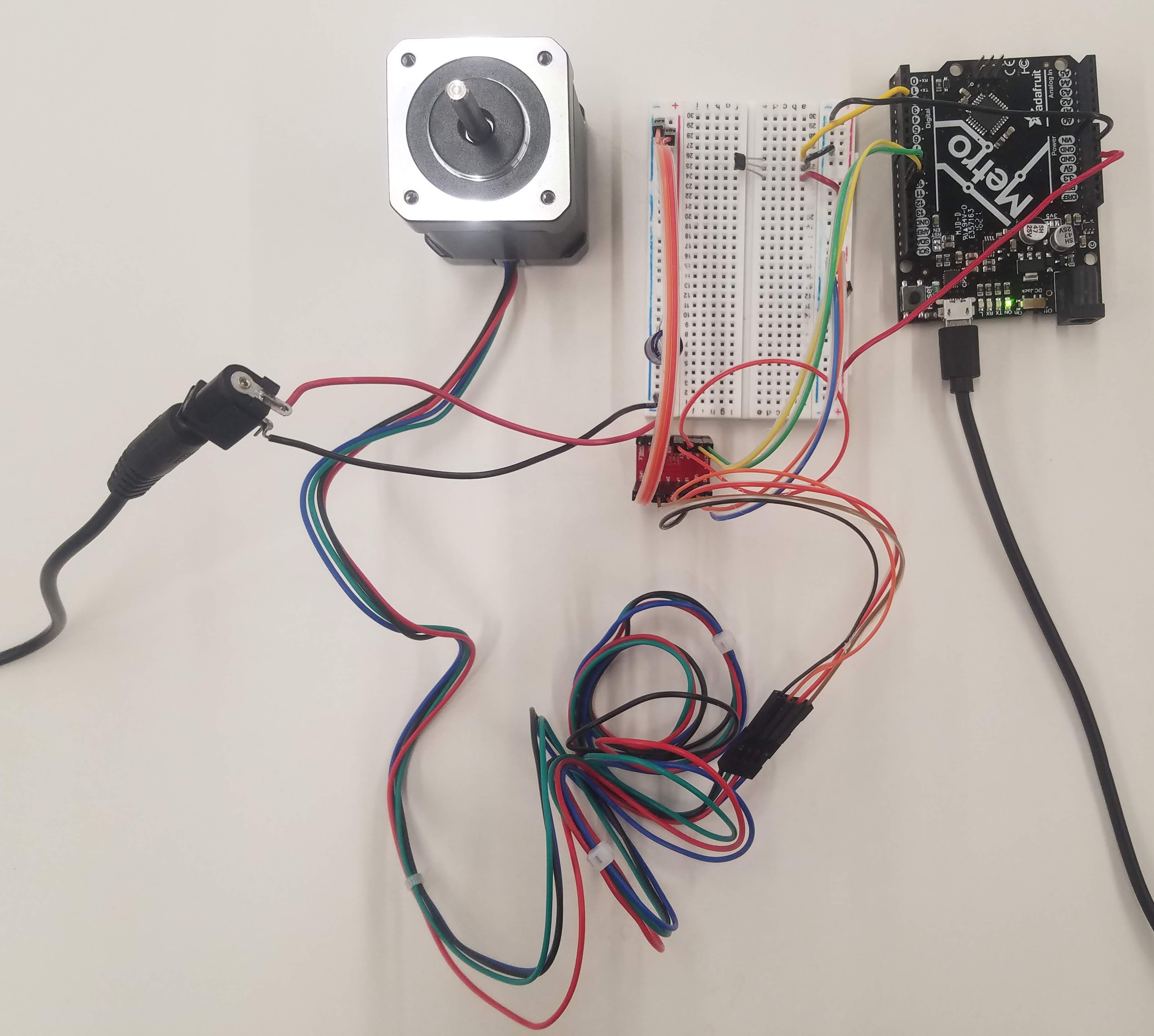
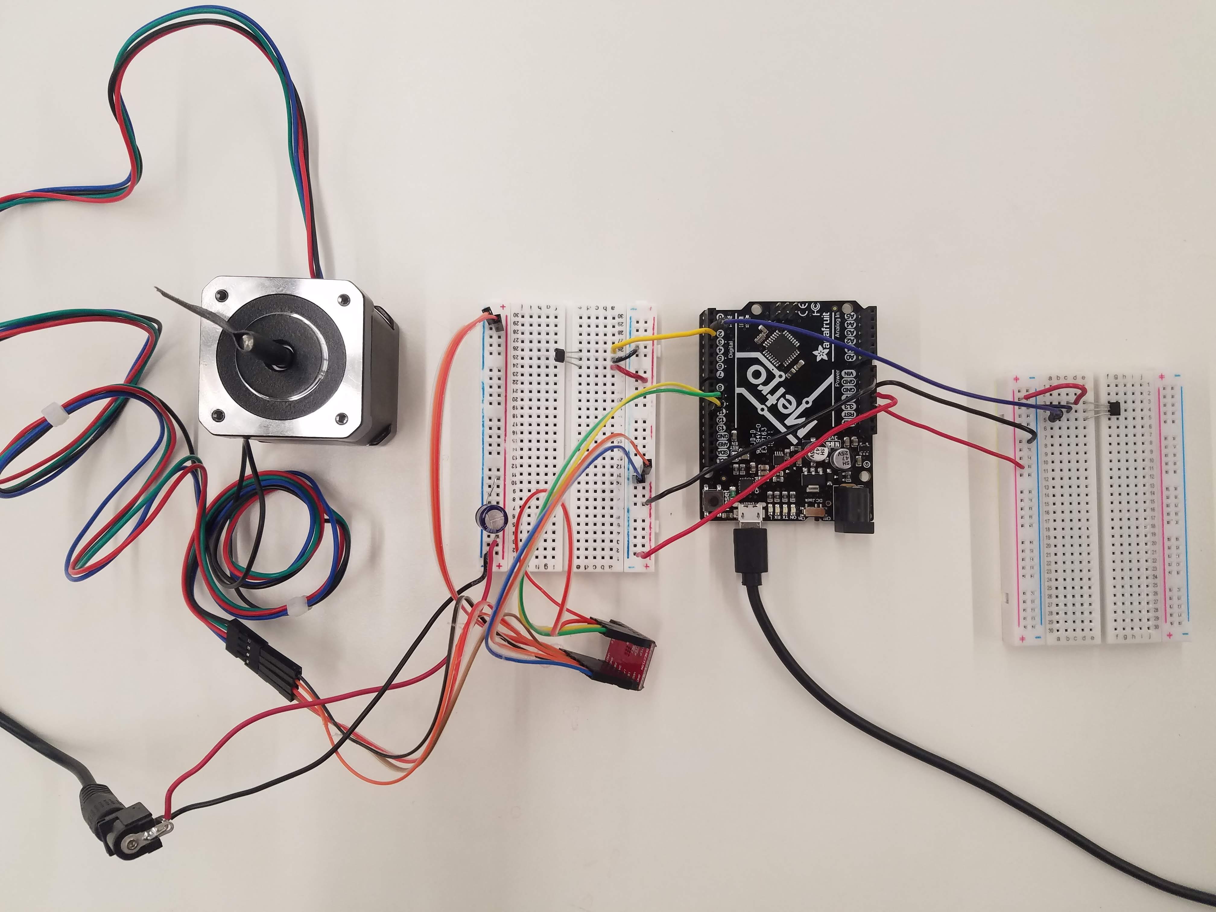
For the second part of this week's project, I followed the tutorial to make a simple machine that could give repeatable results. The goal was to use two magnetic hall sensors attached to pins 2 and 3, unlike the first part where we only used one sensor attached to pin 3. The same wiring schematic shown in part 1 above is used, although the code is very different. As before, an A4988 stepper motor driver was used.
The goal is to have the stepper motor rotate in one direction (CW or CCW) until one of the magnetic hall sensors is triggered, upon which the motor will start rotating in the opposite direction. When the other magnetic hall sensor is triggered, the motor will change direction again, and so on so forth.
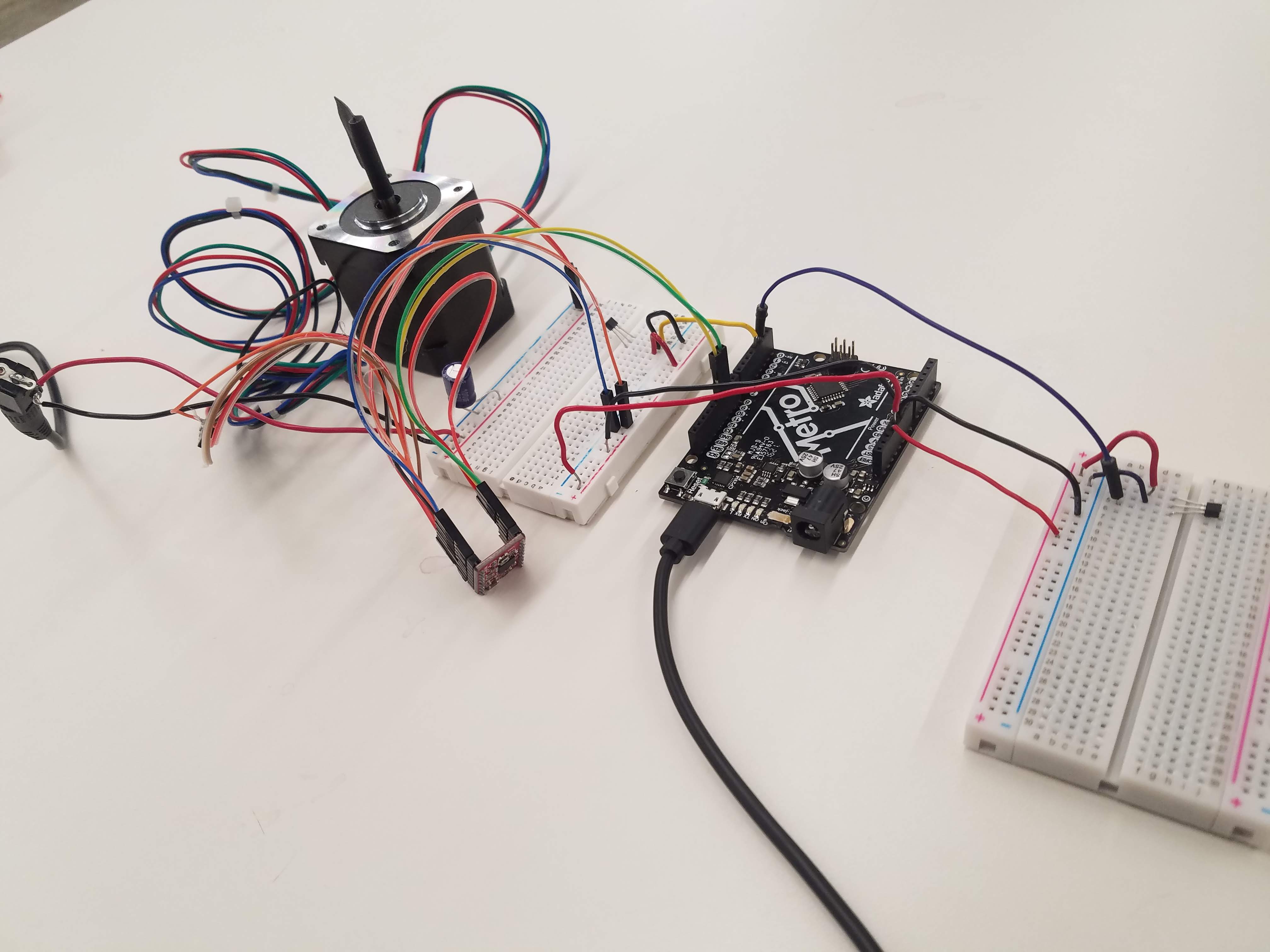
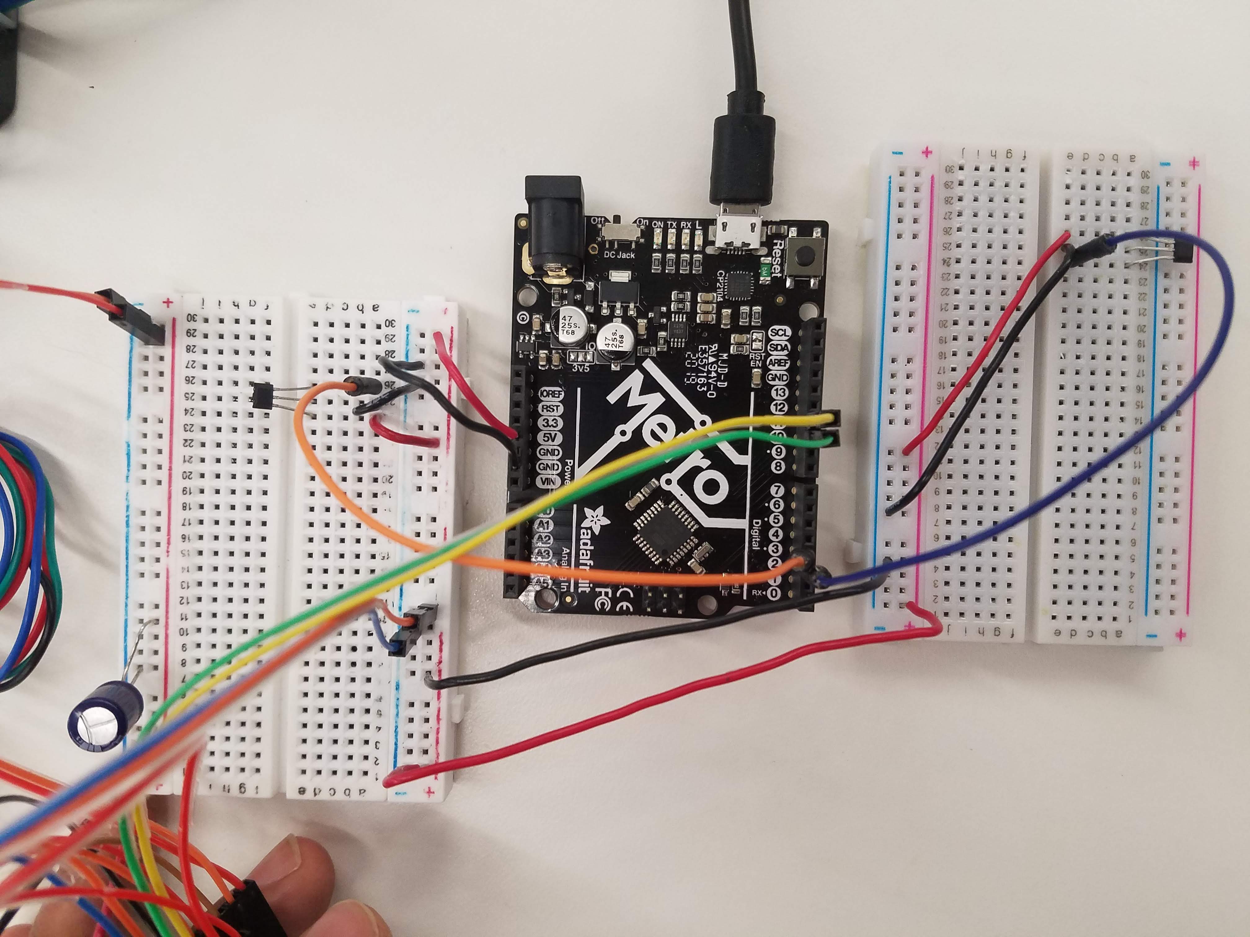
One thing that stood out from this experience was that my Adafruit Metro board stopped working all of a sudden during the first test run of the project. I consulted with Professor Melenbrink and he was able to get me another microcontroller, but we could not identify the issue or what went wrong other than the board started heating up. This was the first wire setup I tried, using the 3.3V pin on the microcontroller to power the magnetic hall sensor (itself attached to pin 2) on the second breadboard:
Wire setup:
Following this, I decided to change the wire setup because I was scared that the second board would stop working if I plugged it into the project as-was. I am unsure if this helped at all, but I changed the wiring such that the second breadboard was powered and grounded by the rails of the first breadboard, which itself was connected to the 5V pin on the microcontroller (versus powered and grounded by the 3.3V and GND pins of the microcontroller, respectively):
Wire setup:
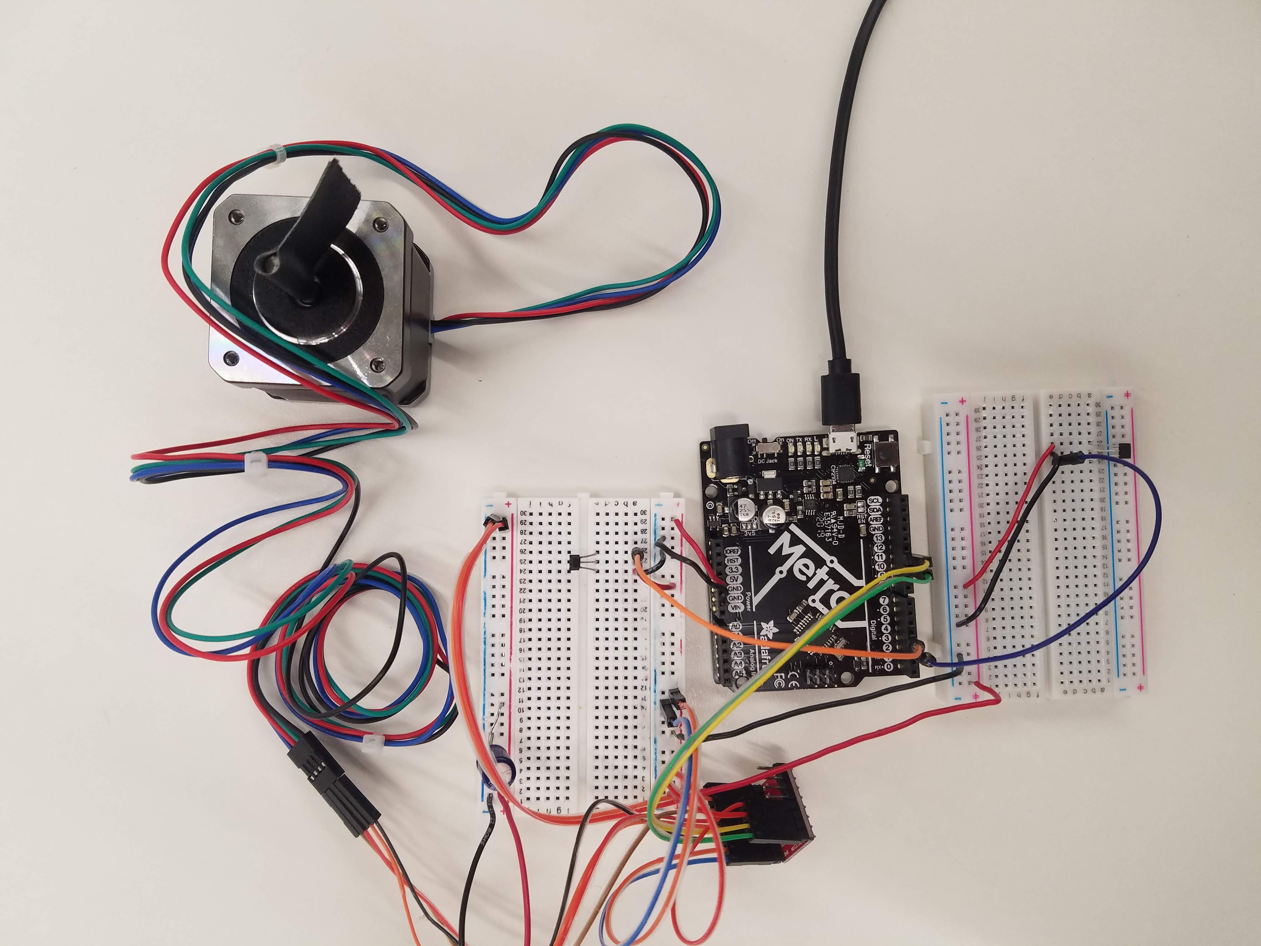
At any rate, the board survived this time around!
Here is the code the micrrocontroller was running:
         /*
           Stepper Motor Limit Switch Demo
           stepper-limit-demo.ino
           Uses Hall Effect sensors as limit switches
           Uses A4988 Stepper Motor Driver module

           DroneBot Workshop 2019
           https://dronebotworkshop.com
         */

         // Define connections
         #define HALL_SENSOR_A      2
         #define HALL_SENSOR_B      3
         #define DIR      10
         #define STEP      11

         // Variables
         int pd = 4000;       // Pulse Delay period
         boolean setdir = LOW; // Set Direction

         // Interrupt Handlers

         void limit_a (){

           // Reverse motor
           setdir = !setdir;

         }

         void limit_b (){

           // Reverse motor
           setdir = !setdir;

         }


         void setup() {

           // Setup the stepper controller pins as Outputs
           pinMode(DIR,OUTPUT);
           pinMode(STEP,OUTPUT);

           // Setup the Hall Effect switches as Inputs
           pinMode(HALL_SENSOR_A, INPUT);
           pinMode(HALL_SENSOR_B, INPUT);

           // Attach interrupt pins to handlers
           attachInterrupt(digitalPinToInterrupt(HALL_SENSOR_A), limit_a, FALLING);
           attachInterrupt(digitalPinToInterrupt(HALL_SENSOR_B), limit_b, FALLING);

         }

         void loop() {

             digitalWrite(DIR,setdir);
             digitalWrite(STEP,HIGH);
             delayMicroseconds(pd);
             digitalWrite(STEP,LOW);
             delayMicroseconds(pd);

         }
The interrupt pins and handlers were new to me. I also had to search up the "attachInterrupt(digitalPinToInterrupt(-,-,-);" lines and admittedly still do not fully understand the function they serve. That said, this part of the project is more applicable to my final project as I can use two magnetic hall sensors at either end of the elevator track and mount a magnet to the elevator box so that it can go back and forth between the two sensors. For more about how this relates to the final project, please see the final project documentation. Also, while I did not add the homing sequence here in void setup(){}, it is definitely possible to do so.
Here is a video of it in action:
As per the assignment, this simple machine made up of a stepper motor, stepper motor driver, microcontroller, two magnetic hall sensors, and a magnet gives repeatable results. Notably, I did not have to reverse the poles of the magnet to change the direction of the stepper motor's rotation like I had to in the first part. That is what I want for my final project, so I will likely be using some version of this code for it.
And that is all for this week. Thank you!
Powered by w3.css
Mohammed Mutaher 2022