Week 7: Electronic Output Devices
This week, we focused on electronic output devices.
We were instructed to use an output device that we had not used yet, and to write a microcontroller program that integrates an input and an output device. Additionally, we were encouraged to avoid using the delay() function and experiment with using either timers or interrupts. Lastly, we were tasked with using an oscilloscope to discover the time domain the output device is operating at.
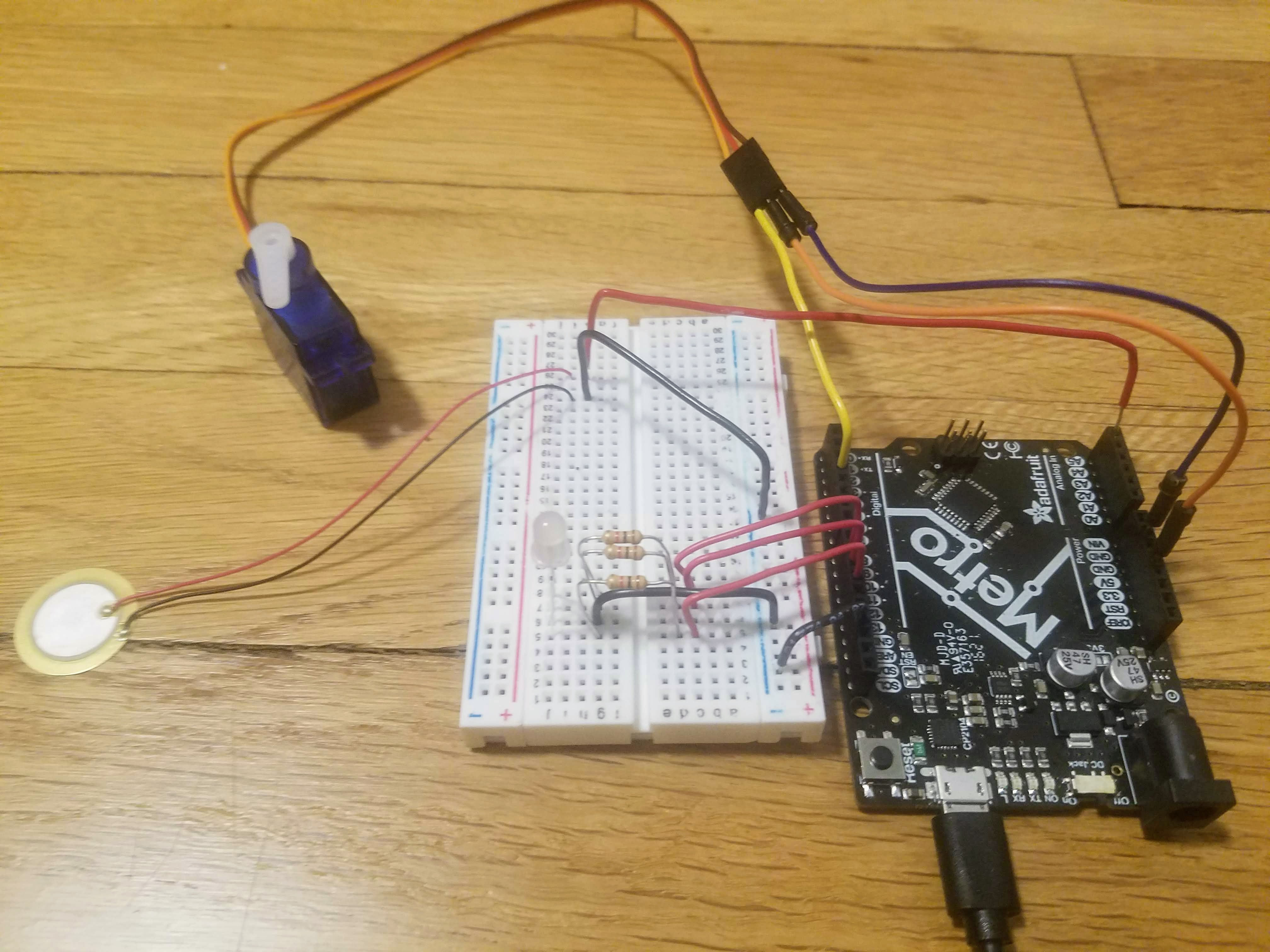
I started this week's assignment with a piezo sensor (input) and green LED (output) setup. I then added a servo motor (output) to the setup so that I could experiment with having two output devices controlled by the same input device. Next, I replaced the green LED with an RGB LED (output) and modified the code accordingly so that the functionality was preserved. Having successfully added the RGB LED to the setup, I experimented with using the millis() function in place of the delay() function. Any relevant resources I consulted while working on this week's assignment are listed at the bottom of the page.
Piezo and LED:
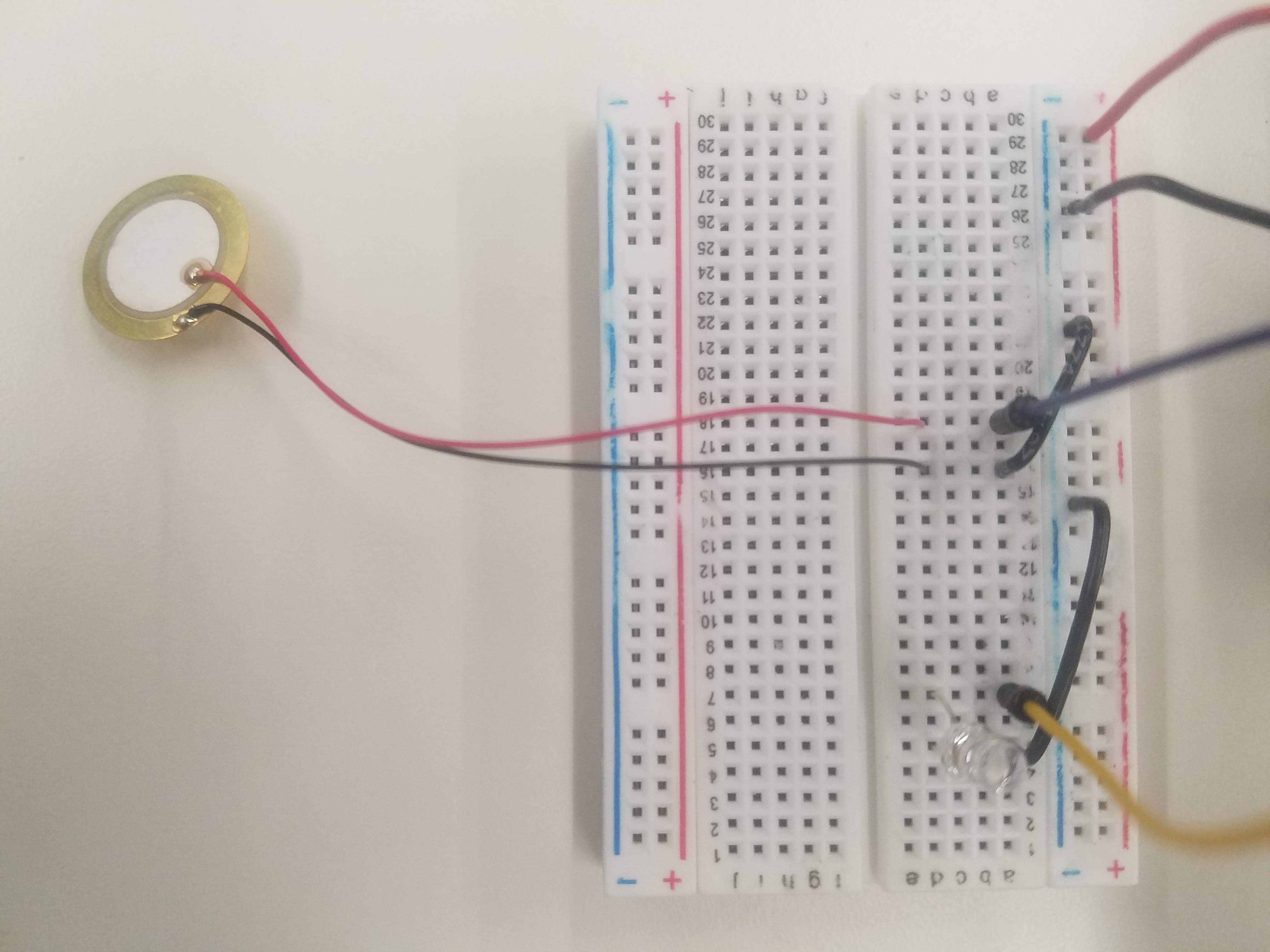
Setup:
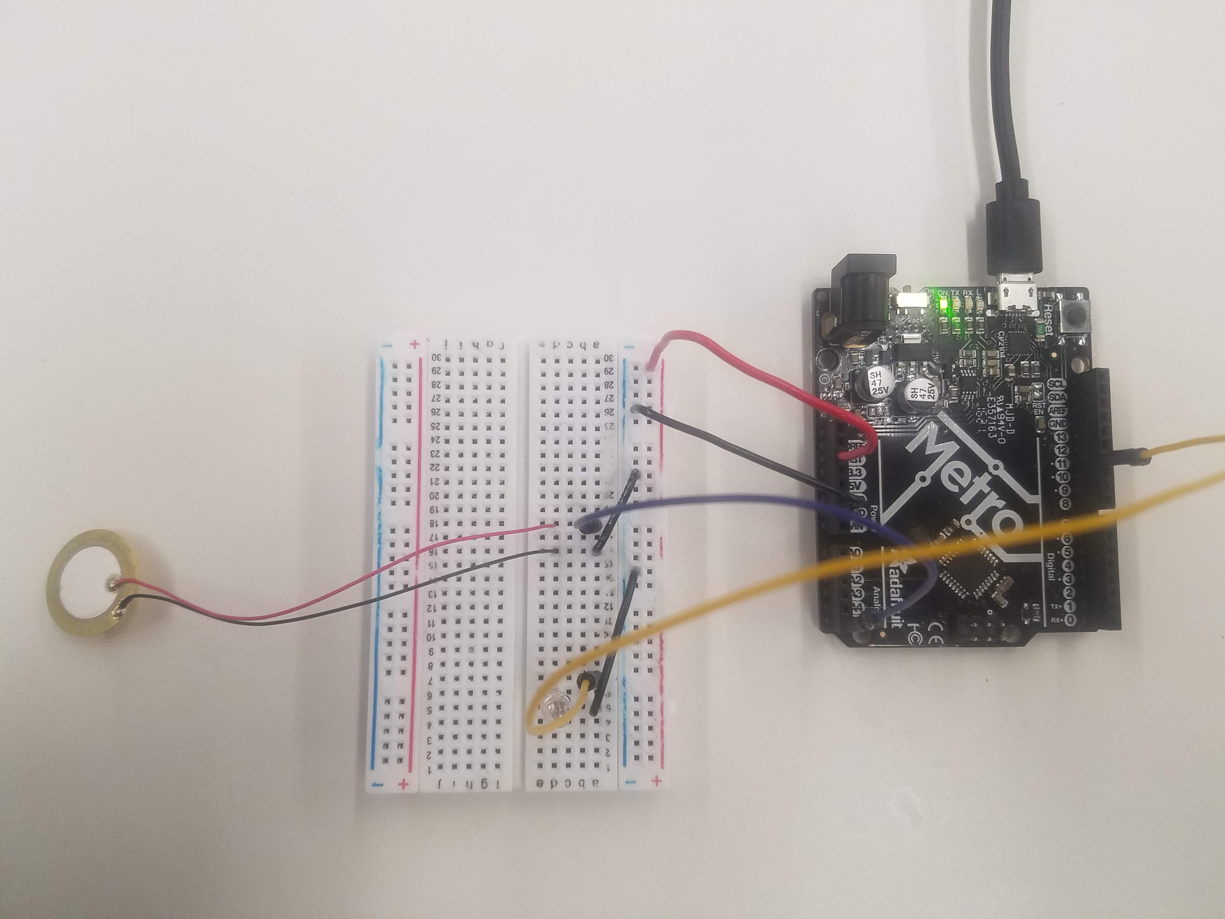
Code:
          int ledPin = 11; // LED on Digital Pin 11
          float ledValue = 0; // The brightness of the LED
          int piezoPin = 5; // Piezo on Analog Pin 5
          int threshold = 120; // The sensor value to reach before activation
          int sensorValue = 0; // A variable to store the value read from the sensor

          void setup() {
          pinMode(ledPin, OUTPUT); // Set the ledPin to an OUTPUT
          // Flash the LED twice to show the program has started
          digitalWrite(ledPin, HIGH); delay(150); digitalWrite(ledPin,
          LOW); delay(150);
          digitalWrite(ledPin, HIGH); delay(150); digitalWrite(ledPin,
          LOW); delay(150);
          }

          void loop() {
          sensorValue = analogRead(piezoPin); // Read the value from the sensor
          if (sensorValue >= threshold) { // If Piezo is touched, turn on the LED
          ledValue = 150;
          }
          analogWrite(ledPin, int(ledValue) ); // Write brightness value to LED
          ledValue = ledValue - 0.05; // Dim the LED slowly
          if (ledValue <= 0) {ledValue = 0;} // Make sure value does not go below zero
          }
Video:
The device works as expected. The goal was to have the LED flash twice upon startup, and then have the LED turn on whenever the piezo sensor was activated (and be off otherwise). I found that touching the piezo sensor was enough to consistently get a signal greater than 120, so even though a the piezo sensor is not intended as a touch sensor, I used it as one for the purpose of the assignment this week.
Piezo, LED, and Servo:
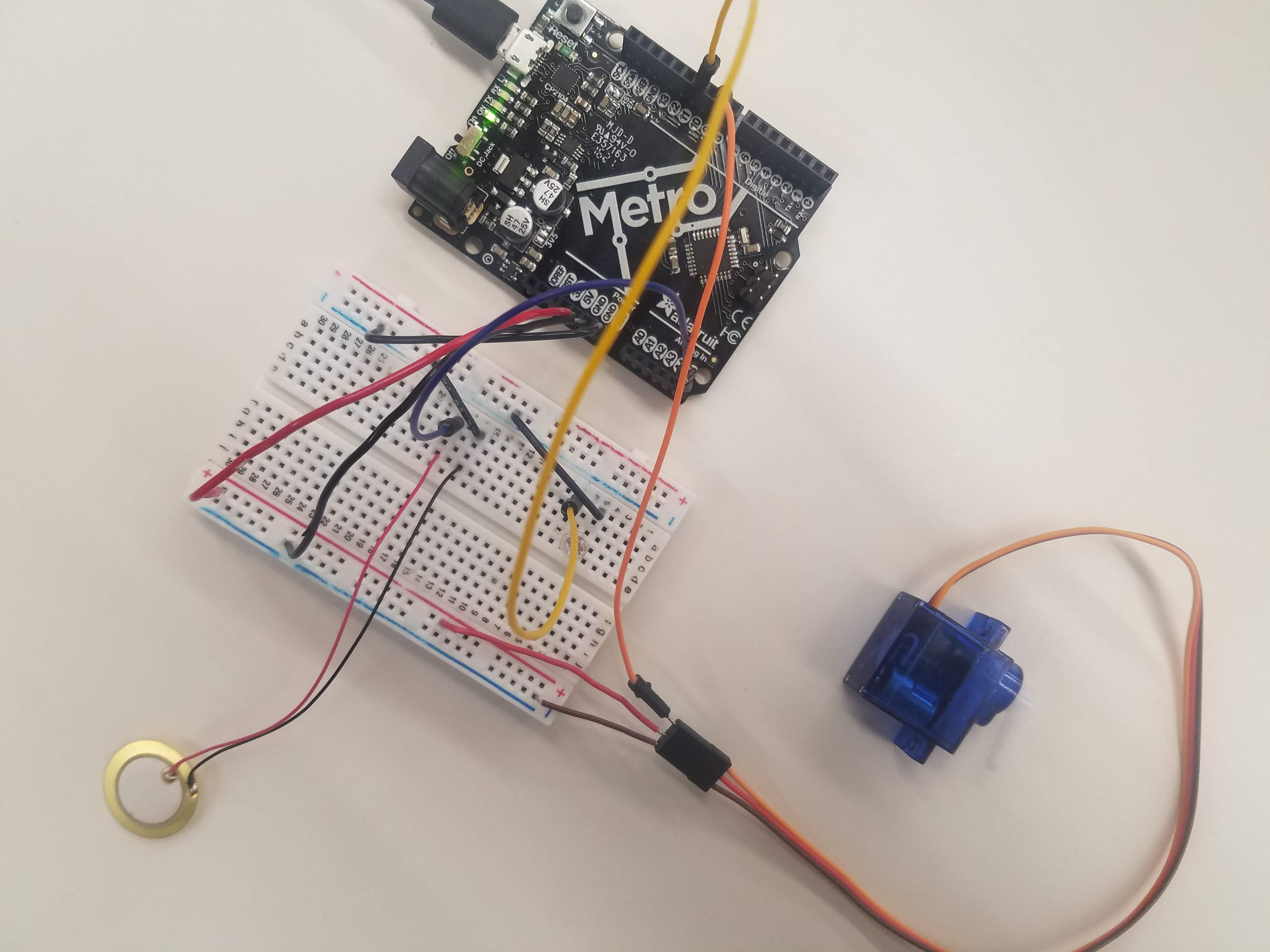
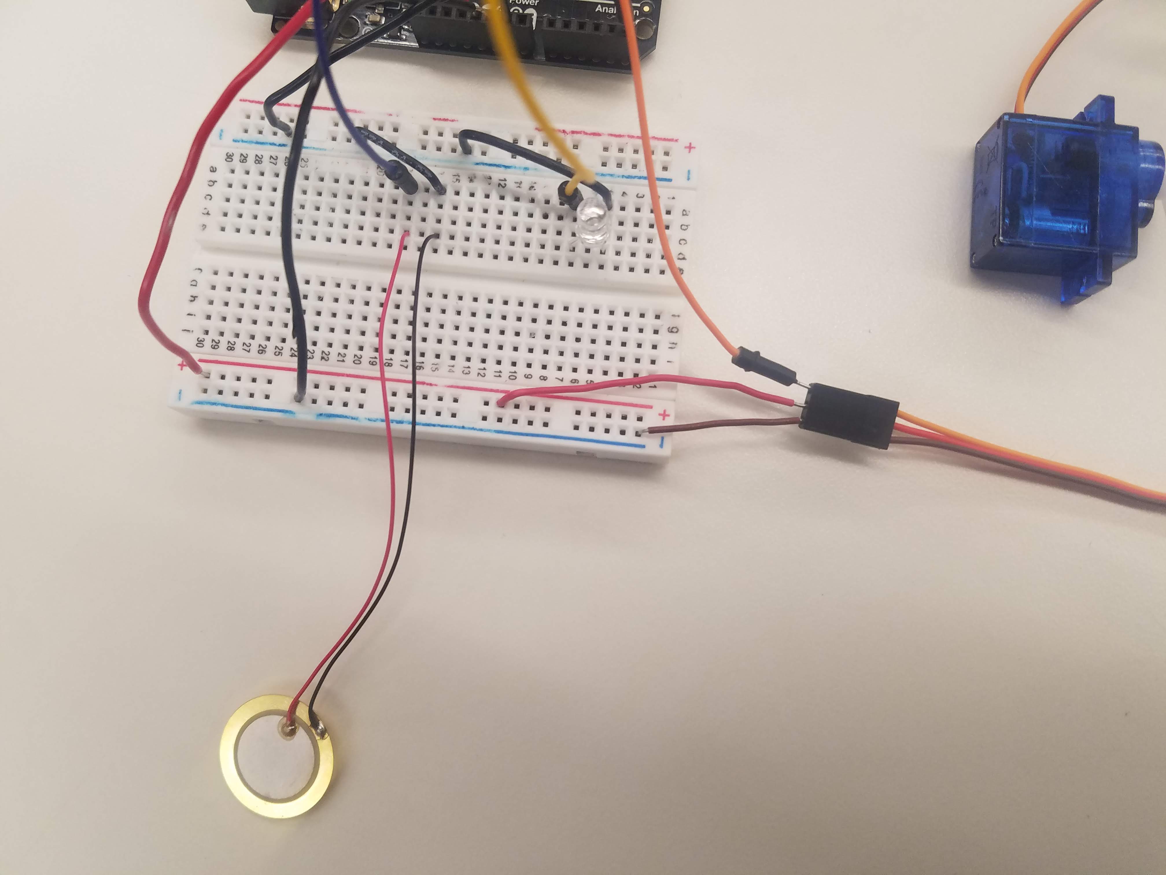
Setup:
Code:
        int ledPin = 11; // LED on Digital Pin 11
        float ledValue = 0; // The brightness of the LED
        int piezoPin = 5; // Piezo on Analog Pin 5
        int threshold = 120; // The sensor value to reach before activation
        int sensorValue = 0; // A variable to store the value read from the sensor
        #include
        Servo myservo;  // Create servo object to control the servo
        int pos = 0;    // Variable to store the servo position

        void setup() {
        pinMode(ledPin, OUTPUT); // Set the ledPin to an OUTPUT
        // Flash the LED twice to show the program has started
        digitalWrite(ledPin, HIGH); delay(150); digitalWrite(ledPin,
        LOW); delay(150);
        digitalWrite(ledPin, HIGH); delay(150); digitalWrite(ledPin,
        LOW); delay(150);
        myservo.attach(9);  // Attaches Servo object to the servo on Digital Pin 9
        }

        void loop() {

        sensorValue = analogRead(piezoPin); // Read the value from the sensor

        if (sensorValue >= threshold) { // If Piezo is touched,
        ledValue = 150; // ...turn on the LED
        pos = 180; // ...set servo position variable to 180
        myservo.write(pos); // Servo moves to position in variable 'pos'
        delay(150); // Waits for the servo to get there
        }

        if (sensorValue <= threshold) { // If Piezo is not touched,
        ledValue = 0; // ...turn off the LED
        pos = 0; // ...set servo position variable to 0
        myservo.write(pos); // Servo moves to position in variable 'pos'
        delay(150); // Waits for the servo to get there
        }

        analogWrite(ledPin, int(ledValue) ); // Write brightness value to LED
        ledValue = ledValue - 0.05; // Dim the LED slowly
        if (ledValue <= 0) {ledValue = 0;} // Make sure value does not go below zero
        }
Video:
The device works as expected. The goal was to have the LED flash twice upon startup, have the LED turn on whenever the piezo sensor was activated (and be off otherwise), and make the servo motor move to the 180 degrees postion whenever the piezo sensor was activated (and return to the 0 degree position otherwise).
Piezo, RGB LED, and Servo using delay():
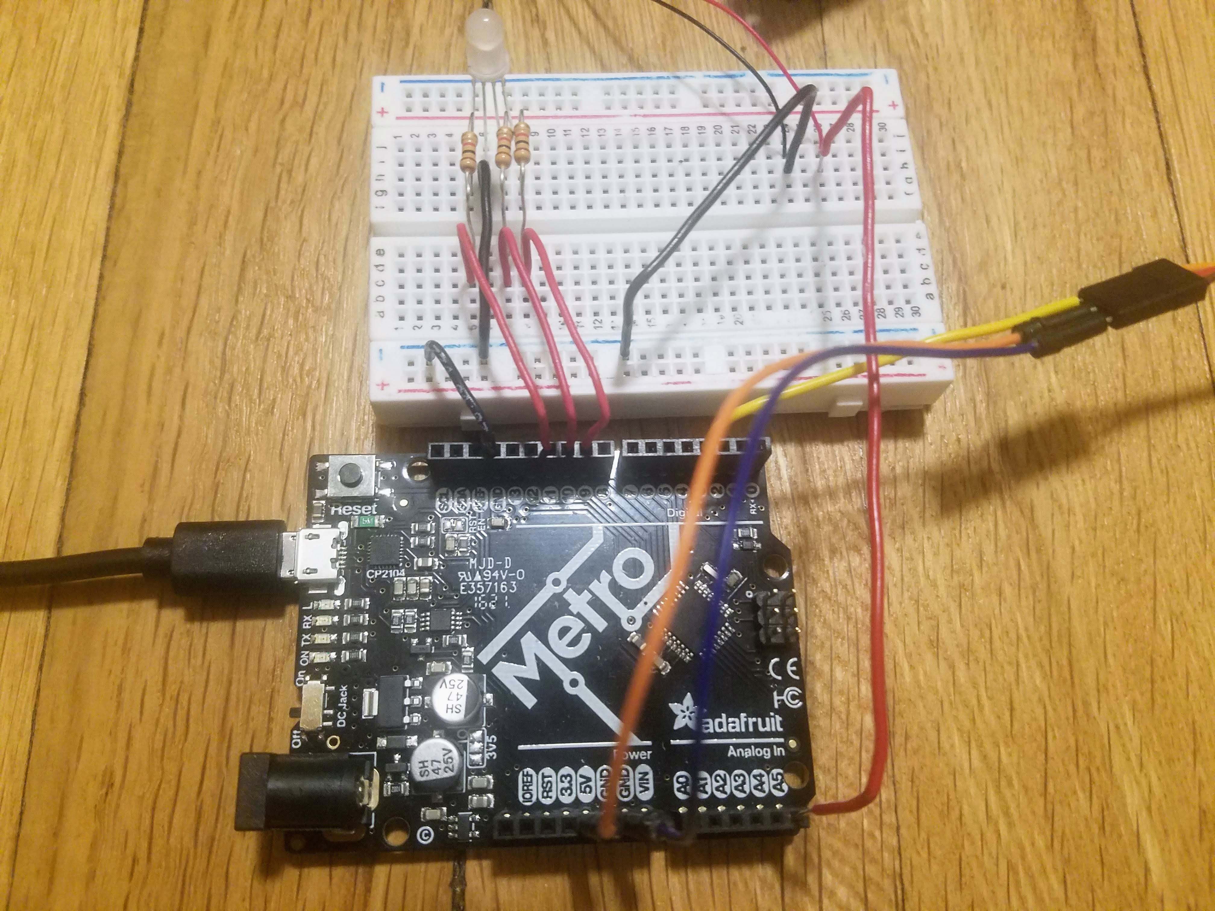
Setup:
Code:
        int red_light_pin= 11;
        int green_light_pin = 10;
        int blue_light_pin = 9;
        int piezoPin = 5; // Piezo on Analog Pin 5
        int threshold = 120; // The sensor value to reach before activation
        int sensorValue = 0; // A variable to store the value read from the sensor
        #include
        Servo myservo;  // Create servo object to control the servo
        int pos = 0;    // Variable to store the servo position

        void RGB_color(int red_light_value, int green_light_value, int blue_light_value) // Allows us to enter specific color values
         {
          analogWrite(red_light_pin, red_light_value);
          analogWrite(green_light_pin, green_light_value);
          analogWrite(blue_light_pin, blue_light_value);
        }

        void setup() {
          pinMode(red_light_pin, OUTPUT);  // Set the red_light_pin to an OUTPUT
          pinMode(green_light_pin, OUTPUT); // Set the green_light_pin to an OUTPUT
          pinMode(blue_light_pin, OUTPUT); // Set the blue_light_pin to an OUTPUT
          // Flash the LED twice to show the program has started
          digitalWrite(green_light_pin, HIGH); delay(150); digitalWrite(green_light_pin,
          LOW); delay(150);
          digitalWrite(green_light_pin, HIGH); delay(150); digitalWrite(green_light_pin,
          LOW); delay(150);
          myservo.attach(3);  // Attaches Servo object to the servo on Digital Pin 3
        }

        void loop() {

        sensorValue = analogRead(piezoPin); // Read the value from the sensor

        if (sensorValue <= threshold) { // If Piezo is not touched,
        RGB_color(0, 0, 255); // ...RGB LED is blue
        pos = 0; // ...set servo position variable to 0
        myservo.write(pos); // Servo moves to position in variable 'pos'
        delay(150); // Waits for the servo to get there
        }

        if (sensorValue >= threshold) { // If Piezo is touched,
        RGB_color(255, 0, 0); // ...RGB LED is red
        pos = 180; // ...set servo position variable to 180
        myservo.write(pos); // Servo moves to position in variable 'pos'
        delay(150); // Waits for the servo to get there
        }
        }
Video:
At this point in the assignment, I decided to get rid of the dim function. The device, however, works as expected. The goal was to have the RGB LED flash green twice upon startup, have the RGB LED turn red whenever the piezo sensor was activated (and turn blue otherwise), and make the servo motor move to the 180 degrees postion whenever the piezo sensor was activated (and return to the 0 degree position otherwise).
Piezo, RGB LED, and Servo using millis():
Setup (same as before):
Code:
I borrowed the code from the "Multi-tasking the Arduino - Part 1: A classy solution" Adafruit tutorial for the millis() function. I modified the code from the tutorial and added parts from my arduino program into it to get the program below.
        int piezoPin = 5; // Piezo on Analog Pin 5
        int threshold = 120; // The sensor value to reach before activation
        int sensorValue = 0; // A variable to store the value read from the sensor
        #include

        class Flasher
        {
          // Class Member Variables
          // These are initialized at startup
          int ledPin;      // the number of the LED pin
          long OnTime;     // milliseconds of on-time
          long OffTime;    // milliseconds of off-time

          // These maintain the current state
          int ledState;                 // ledState used to set the LED
          unsigned long previousMillis;   // will store last time LED was updated

          // Constructor - creates a Flasher
          // and initializes the member variables and state
          public:
          Flasher(int pin, long on, long off)
          {
          ledPin = pin;
          pinMode(ledPin, OUTPUT);

          OnTime = on;
          OffTime = off;

          ledState = LOW;
          previousMillis = 0;
          }


          void Update()
          {
            // check to see if it's time to change the state of the LED
            unsigned long currentMillis = millis();

            if((ledState == HIGH) && (currentMillis - previousMillis >= OnTime))
            {
              ledState = LOW;  // Turn it off
              previousMillis = currentMillis;  // Remember the time
              digitalWrite(ledPin, ledState);  // Update the actual LED
            }
            else if ((ledState == LOW) && (currentMillis - previousMillis >= OffTime))
            {
              ledState = HIGH;  // turn it on
              previousMillis = currentMillis;   // Remember the time
              digitalWrite(ledPin, ledState);   // Update the actual LED
            }
          }
        };


        class Sweeper
        {
          Servo servo;              // the servo
          int pos;              // current servo position
          int increment;        // increment to move for each interval
          int  updateInterval;      // interval between updates
          unsigned long lastUpdate; // last update of position


        public:
          Sweeper(int interval)
          {
            updateInterval = interval;
            increment = 1;
          }

          void Attach(int pin)
          {
            servo.attach(pin);
          }

          void Detach()
          {
            servo.detach();
          }

          void Update()
          {
            if((millis() - lastUpdate) > updateInterval)  // time to update
            {
              lastUpdate = millis();
              pos += increment;
              servo.write(pos);
              Serial.println(pos);
              if ((pos >= 180) || (pos <= 0)) // end of sweep
              {
                // reverse direction
                increment = -increment;
              }
            }
          }
        };

        Flasher led1(11, 1000, 1000); // Red
        Flasher led2(10, 1000, 1000); // Blue
        Flasher led3(9, 1000, 1000); // Green

        Sweeper sweeper1(15);


        void setup()
        {
          Serial.begin(9600);
          sweeper1.Attach(3);
        }


        void loop()
        {
          sensorValue = analogRead(piezoPin); // Read the value from the sensor
          sweeper1.Update(); // Servo will move back and forth from 0 to 180 degrees

          if (sensorValue <= threshold) { // If Piezo is not touched,
          led1.Update(); // ...LED is red
          }

          if (sensorValue >= threshold) { // If Piezo is touched,
          led3.Update(); // ...LED is blue
          }
        }
Video:
When a delay() statement is being run the program cannot respond to inputs or process any data, and the user cannot change any outputs. The millis() function can be used in place of the delay() function and is ideal for repetitive timed events. It also avoids the aforementioned shortcomings of the delay() function.
For this iteration of the program, I wanted to experiment mainly with the millis() function. I deleted the code that used the delay() function to flash the RGB LED twice upon startup because replacing that instance of the delay() function with millis() resulted in the RGB LED constantly flashing green for the set on and off times. Nonetheless, I left "Flasher led3(9, 1000, 1000);" in the code so that I could easily change the color of the RGB LED to green if I wanted to. The goal was to have the RGB LED flash red (on for one second, off for one second) whenever the piezo sensor was activated (and flash blue otherwise) and make the servo motor move back and forth constantly between the 0 and 180 degrees postion. I found it interesting that the RGB LED would flash both red and blue when the piezo sensor was activated, and that it only flashed red when the piezo sensor was not activated. It flashing both blue and red when activated was unintended, and I spent hours trying to get it to flash only blue when the piezo sensor was activated without any success. For example, I tried creating a "Flasher led1b(11, 0, 0);" instance and placing it before "led3.Update();" in the "if (sensorValue >= threshold){}" statement but that unfortunately did not work. Another thing I tried was placing the "if (sensorValue >= threshold){}" before the "if (sensorValue <= threshold){}" statement, but that had no effect either. The only explanation I can think of is that the millis() function is not intended to be interrupted after being called, but this explanation does not explain why the RGB LED does not continue to flash red and blue after the piezo sensor is activated once and then left alone. Regarding the servo, I decoupled it from the piezo sensor input and ran it independent of an "if" statement under "void loop(){}". As intended, the servo consistently swept from 0 to 180 and back at regular intervals while the program was running.
Using the oscilloscope:
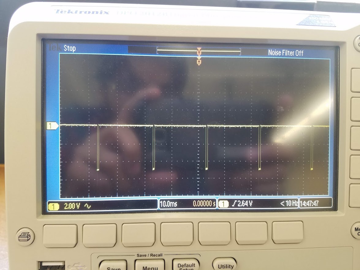
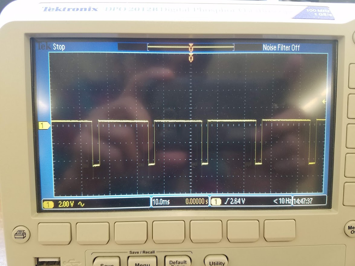
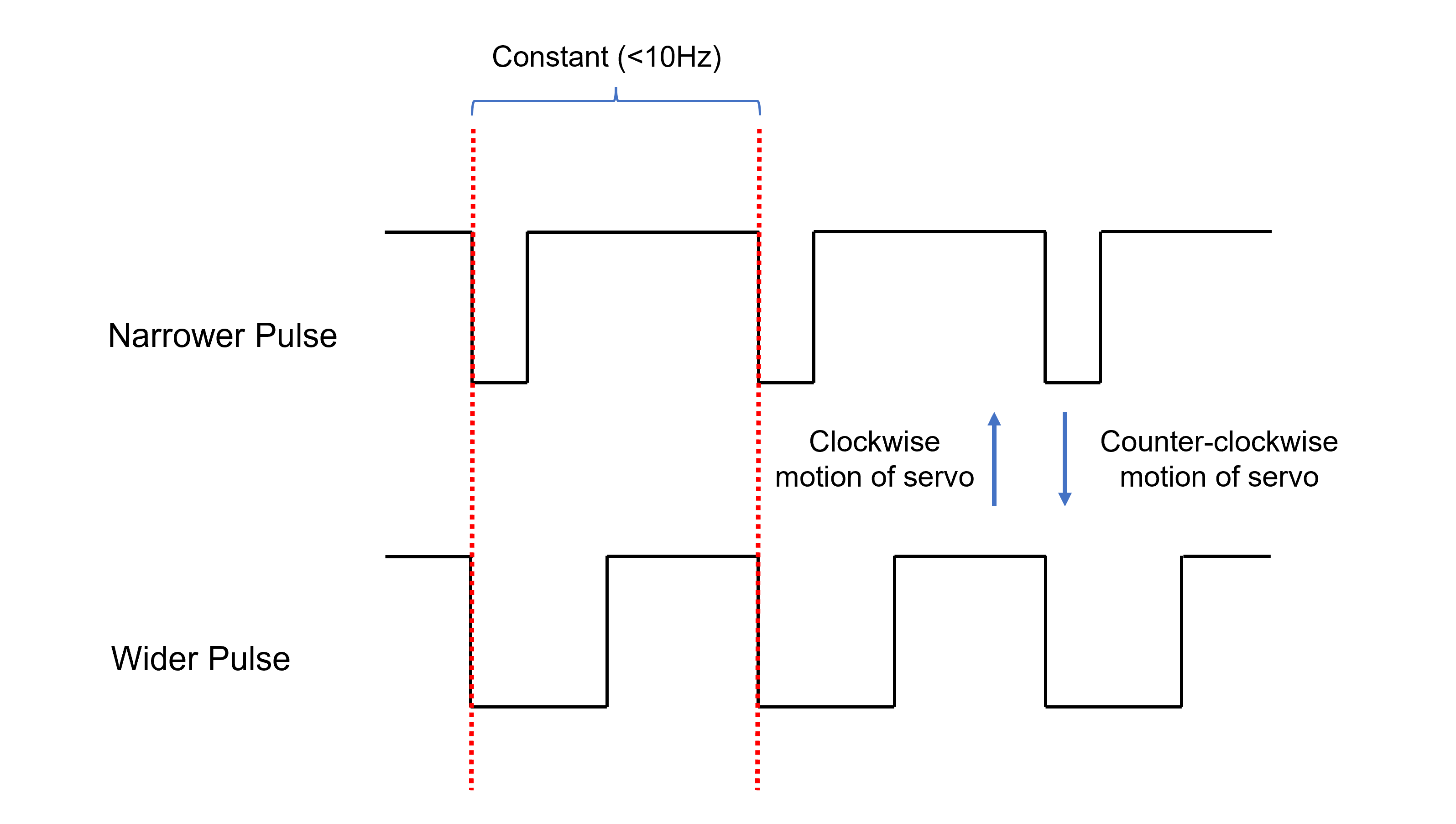
I was able to measure the time domain at which the servo motor was operating in the final iteration of this week's project (see "Piezo, RGB LED, and Servo using millis()" section above). Chris helped me with this section of the assignment. Basically, the arduino sends pulse lengths that the servo motor interprets as a position, and it moves accordingly. As shown in the video, clockwise motion of the servo motor corresponds to a narrower pulse on the oscilloscope and counter-clockwise motion corresponds to a wider pulse:
Video:
Although the pulse lengths change depending on motor's position, the difference between the start of each pulse is the same. Since the difference between the start of each pulse is constant, the servo motor is operating on a fixed clock. The speed, as indicated on the display, is less than 10 Hertz (<10Hz).
Lastly, I made a graphic summarizing all the information in this section:
And that is all for this week. Thank you!
Sources referenced:
- https://arduinogetstarted.com/tutorials/arduino-rgb-led
- https://create.arduino.cc/projecthub/muhammad-aqib/arduino-rgb-led-tutorial-fc003e
- https://create.arduino.cc/projecthub/patatoDude/rgb-led-basics-a6fe50
- https://create.arduino.cc/projecthub/sarful/arduino-workshop-piezo-knock-sensor-da6d83?ref=user&ref_id=520827&offset=10
- https://forum.arduino.cc/t/rgb-blinkg-with-millis/513728/6
- https://roberthart56.github.io/SCFAB/SC_lab/Output_Devices/Light/led/index.html
- https://www.youtube.com/watch?v=BYKQ9rk0FEQ
Powered by w3.css
Mohammed Mutaher 2022